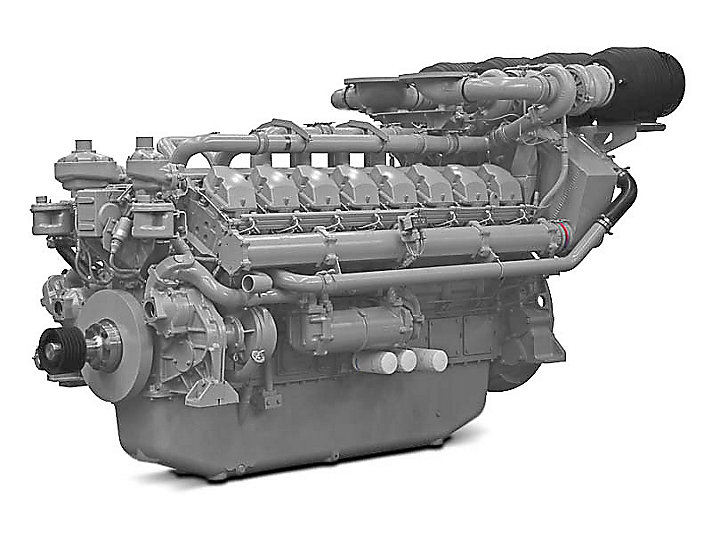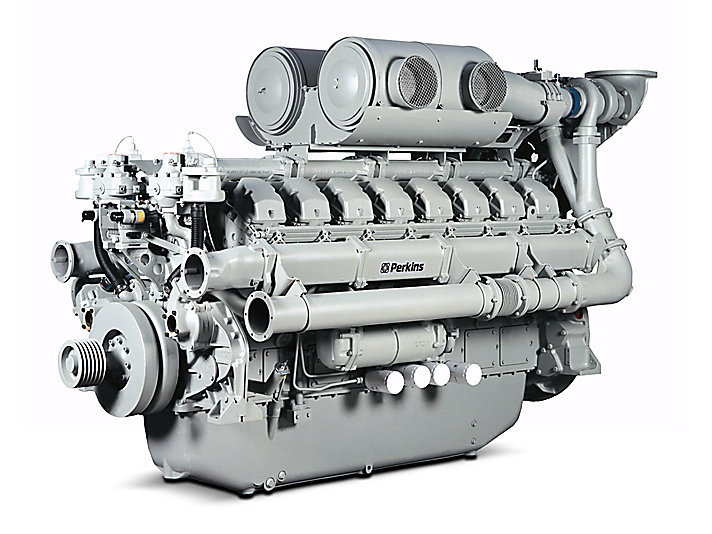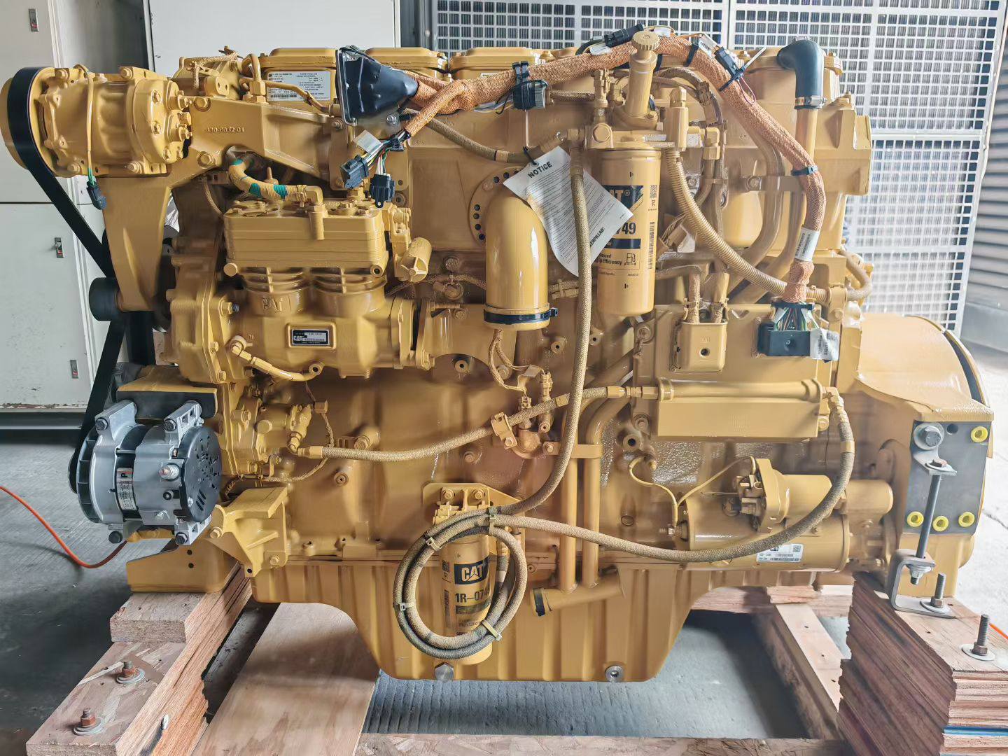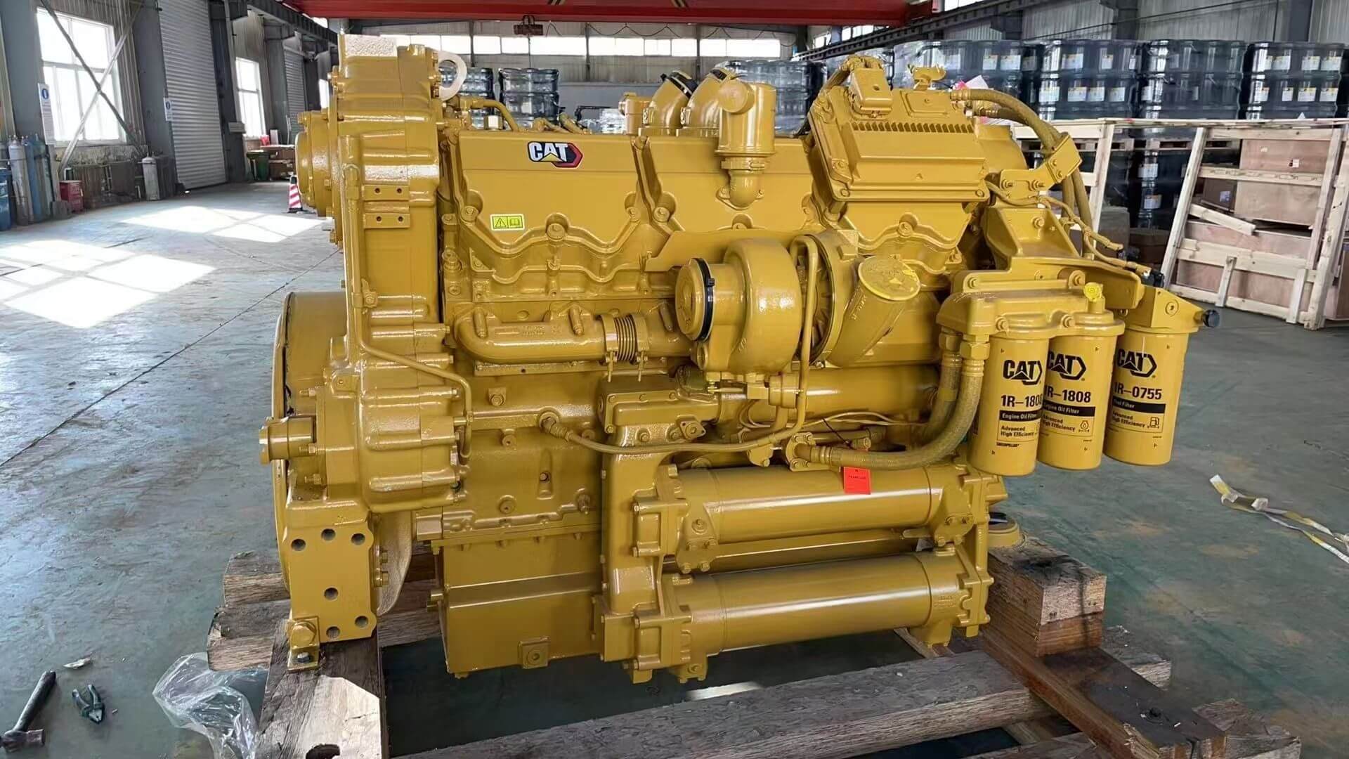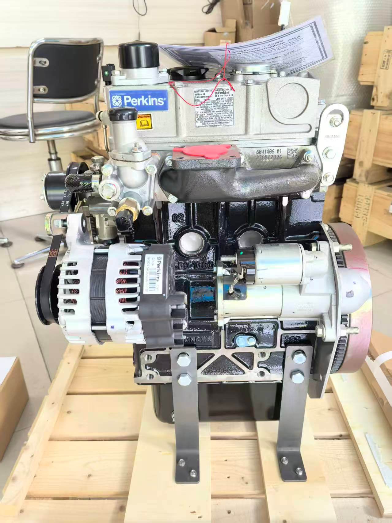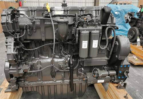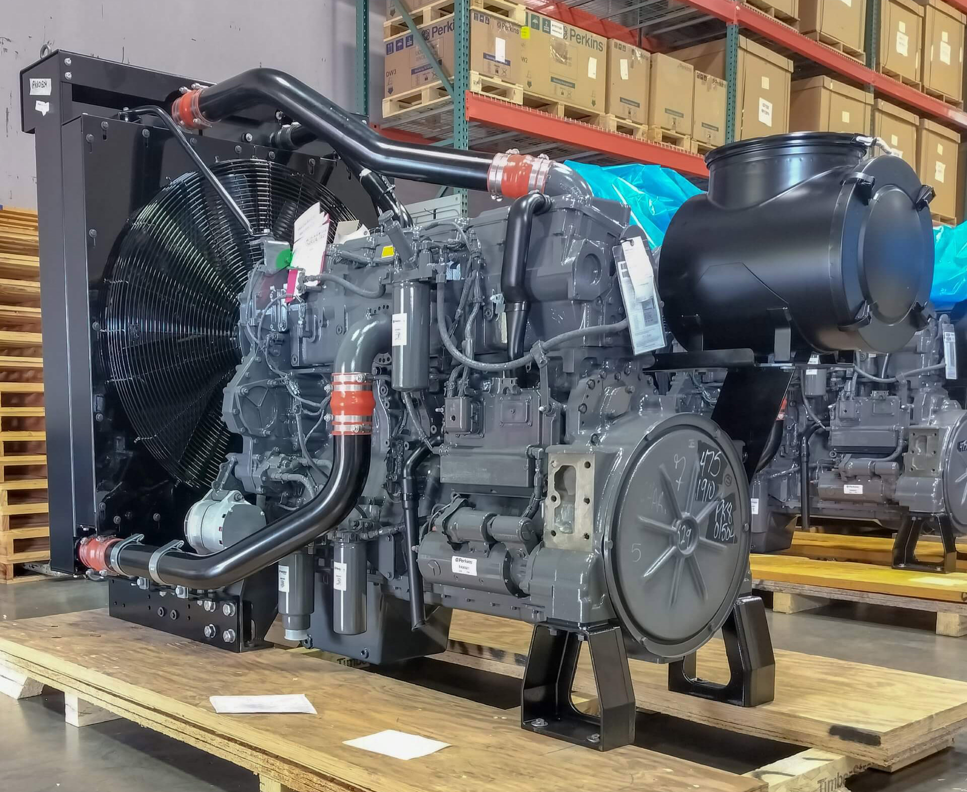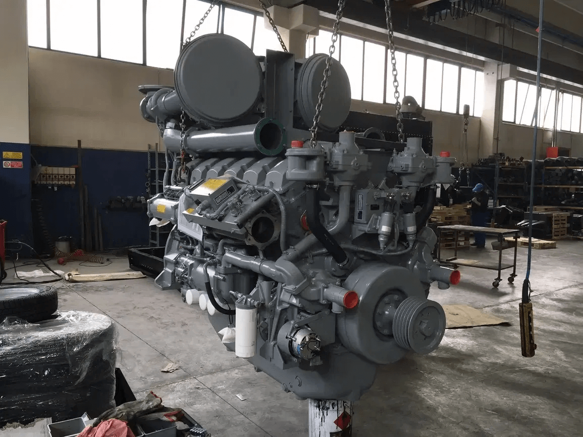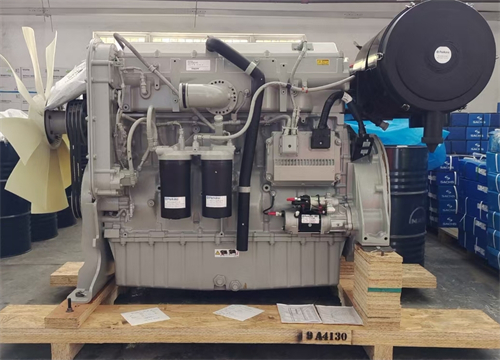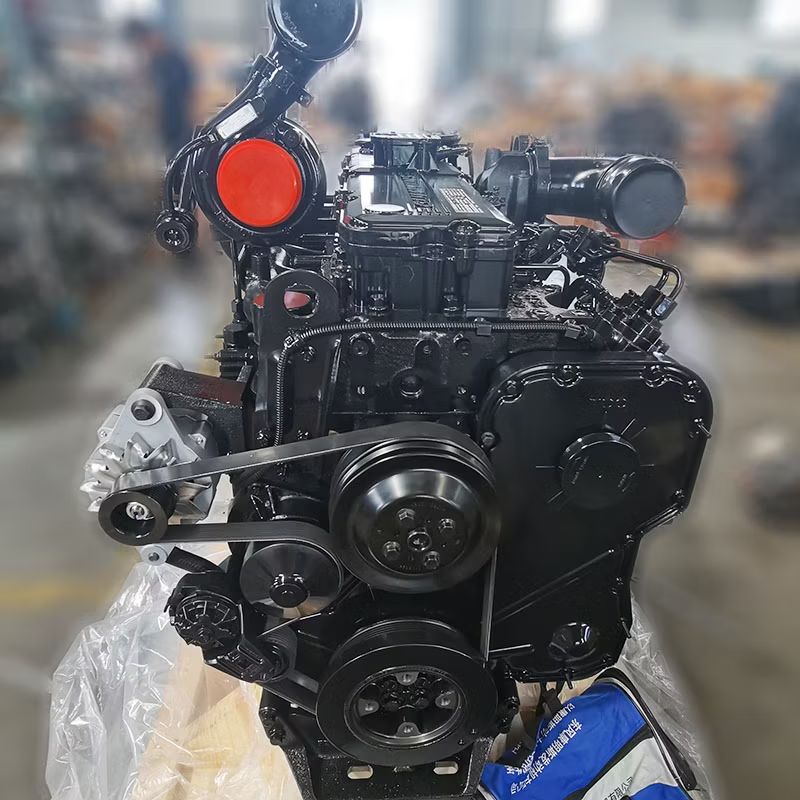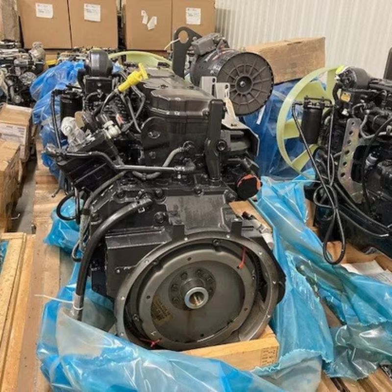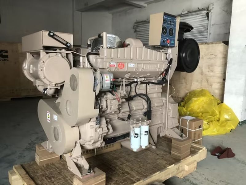

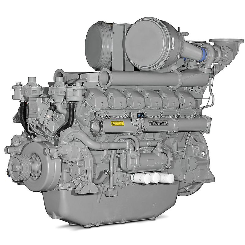
The Perkins 4012-46TAG3A is a 45.842-litre V12 diesel engine for high-output 1500 rpm / 50 Hz generator sets. The confirmed DGDM6134 / DGDM0083 / DGDM1419 configuration is rated at 1710 kVA prime and 1880 kVA standby, corresponding to 1368 kWe and 1504 kWe at a stated power factor of 0.8.
This is the upper published output tier covered by the current 4012-46TAG product pages. It uses turbocharging, air-to-air charge cooling, individual four-valve cylinder heads, unit fuel injectors and electronic speed governing without a full engine-mounted ECM. Selection requires the complete Build List, ESN, rated speed, cooling package, supply scope and destination requirements.
The Confirmed Page Rating Is 1710/1880 kVA at 1500 rpm
The 1710 kVA prime and 1880 kVA standby figures on this page apply to the confirmed 1500 rpm / 50 Hz DGDM6134, DGDM0083 and DGDM1419 Build List family.
The broader 4012-46TAG3A model name also appears on separate 1800 rpm Build Lists. Those versions are not the same engine build and should not inherit the 1500 rpm ratings without their own Perkins power documentation.
| Identification Item | Confirmed Page Configuration |
|---|---|
| Engine Model | Perkins 4012-46TAG3A |
| Primary Build Lists | DGDM6134 / DGDM0083 / DGDM1419 |
| Updated Build Lists | DGD6134 / DGD0083 / DGD1419 |
| Rated Speed | 1500 rpm |
| Generator Frequency | 50 Hz |
| Prime Rating | 1710 kVA / 1368 kWe |
| Standby Rating | 1880 kVA / 1504 kWe |
Engine and Generator Output
Engine power and generator-set output are related but are not the same value. The generator kVA and kWe figures account for the alternator and the stated electrical power factor, while gross and net engine power describe mechanical output at the engine.
| Duty | Gross Engine Power | Net Engine Power | Generator Output | Electrical Output |
|---|---|---|---|---|
| Prime | 1521 kW (2040 hp) | 1440 kW (1931 hp) | 1710 kVA | 1368 kWe |
| Standby | 1664 kW (2231 hp) | 1583 kW (2123 hp) | 1880 kVA | 1504 kWe |
Why Generator Suppliers May Advertise Different kVA Figures
A genset supplier may publish a different final kVA value because alternator efficiency, power factor, temperature rise, site altitude, ambient temperature and package losses affect the released generator-set rating.
Confirm whether a quoted output refers to engine gross power, engine net power, generator kWe, generator kVA, prime duty or standby duty before comparing suppliers.
Prime and Standby Are Different Operating Duties
The supplied duty description states that the 1710 kVA prime rating supports variable-load operation with an average load factor not exceeding 80% over 24 hours. It also states that a 10% overload may be used for one hour in every twelve hours.
The 1880 kVA standby rating is described for operation during failure of the normal power source, with annual use limited to 500 hours and no overload permitted.
| Duty Decision | Supplied Operating Direction |
|---|---|
| Prime Power | Variable load with an average load factor not exceeding 80% over 24 hours |
| Prime Overload | 10% overload for one hour in every twelve hours |
| Standby Power | Emergency operation during failure of the normal power source |
| Standby Annual Use | Up to 500 hours per year in the supplied duty description |
| Standby Overload | No overload permitted |
Final duty approval should follow the rating sheet and operating standard applicable to the exact engine and generator-set configuration. Site owners should define annual operating hours, load variation and overload requirements before selecting a rating.
Do Not Treat 1880 kVA as a Continuous Rating
The numerical table supplied for this engine provides prime and standby ratings only. It does not provide a separate continuous-power kVA or kWe value.
A project requiring continuous baseload operation should request the applicable continuous-duty rating sheet. The 1880 kVA standby figure must not be reused as a continuous output.
| Rating Type | Published Value on This Page |
|---|---|
| Prime | 1710 kVA / 1368 kWe |
| Standby | 1880 kVA / 1504 kWe |
| Continuous | Not provided in the supplied power table |
TAG3A Compared with the Dual-Speed TAG2A
The Perkins 4012-46TAG2A and TAG3A share the same stated 45.842-litre V12 architecture, but their Build Lists, output levels and speed configurations are different.
| Model | Confirmed Speed Direction | Prime Output | Standby Output | Main Build Prefix |
|---|---|---|---|---|
| 4012-46TAG2A | 1500 / 1800 rpm under the principal dual-speed Build List | 1505 / 1511 kVA | 1657 / 1661 kVA | DGB / DGBM |
| 4012-46TAG3A | 1500 rpm for the configuration covered on this page | 1710 kVA | 1880 kVA | DGD / DGDM |
TAG3A provides a higher 50 Hz output tier, but it is not an automatic replacement for TAG2A. Alternator size, coupling, radiator, foundation, exhaust system, control wiring and transient-load performance must be reviewed before an upgrade is approved.
Main Build Lists: DGDM6134, DGDM0083 and DGDM1419
DGDM6134, DGDM0083 and DGDM1419 are identified as the original Perkins Build List designations assigned in 2008. DGD6134, DGD0083 and DGD1419 are the corresponding shortened designations used for engines produced in later batches.
| Build List Group | Identification | Confirmed Rated Speed |
|---|---|---|
| DGDM6134 / DGDM0083 / DGDM1419 | Original Perkins designations | 1500 rpm |
| DGD6134 / DGD0083 / DGD1419 | Updated shortened designations | Same stated engine specification |
The supplied information treats the original and shortened designations as equivalent for the stated specification and parts compatibility. The complete Engine Serial Number remains necessary because it identifies the production record, installed options and component revisions of the individual engine.
Information to Record from the Nameplate
- Complete engine model: 4012-46TAG3A
- Complete Build List beginning with DGD or DGDM
- Complete Engine Serial Number
- Rated speed shown on the engine record
- Temperate or tropical cooling package
- Fuel-oil cooling option when fitted
- Electro unit or ElectropaK supply scope
- Original generator-set manufacturer and model
The engine dataplate is normally mounted on the rocker-cover or timing-case area. A clear photograph of the full plate is preferable to manually copied identification data.
1500 and 1800 rpm TAG3A Versions Are Separate Builds
The 4012-46TAG3A designation also appears on separate 1800 rpm versions. These engines use different Build Lists and are not field-interchangeable with the confirmed 1500 rpm configuration.
| Version | Build List | Rated Speed | Output Provided in the Source |
|---|---|---|---|
| 4012-46TAG3A (E/U) | DGDM6134 / DGDM0083 / DGDM1419 | 1500 rpm | 1710 kVA prime / 1880 kVA standby |
| 4012-46TAG3A (E/U), India | DGDM6134S / DGDM0083S / DGDM1419S | 1500 rpm | Not provided |
| 4012-46TAG3A, India | DGDM6059S / DGDM1068S | 1800 rpm | Not provided |
| 4012-46TAG3A (E/P) | DGDM6051 | 1800 rpm | Not provided |
The 1710/1880 kVA rating must not be assigned automatically to DGDM6059S, DGDM1068S, DGDM6051 or the India-specific 1500 rpm versions. Each quotation should follow the rating documents for the exact Build List.
Mechanical Injection with Electronic Speed Governing
The 4012-46TAG3A uses unit fuel injectors controlled through an actuator and electronic governor rather than a full engine-mounted ECM. It is therefore more accurately described as a mechanically injected engine with electronic speed governing.
This distinction affects genset integration, replacement-parts selection and diagnostic procedures. Buyers should not assume that all start, stop, protection, communication and fault-recording functions are contained in an engine ECM.
| Control Area | Integration Requirement |
|---|---|
| Electronic Governor | Confirm governor model, supply voltage and speed-setting interface |
| Actuator | Confirm actuator type, linkage, response and supplied harness |
| Speed Signal | Confirm the magnetic pickup or applicable speed-sensing arrangement |
| Start and Stop Logic | Confirm how the genset controller commands engine starting and shutdown |
| Engine Protection | Confirm oil-pressure, coolant-temperature, overspeed and emergency-stop circuits |
| Parallel Operation | Confirm governor load-sharing and synchronization interfaces |
| Diagnostic Method | Use the wiring and control documentation for the exact Build List |
V12 Mechanical Platform
The 4012-46TAG3A uses a 12-cylinder, 60-degree vee architecture with a displacement of 45.842 litres. The engine is turbocharged, air-to-air charge cooled and uses direct fuel injection.
| Mechanical Parameter | Specification |
|---|---|
| Configuration | Electro unit and ElectropaK |
| Cylinder Arrangement | 12 cylinders, 60° vee |
| Displacement | 45.842 L (2979 in³) |
| Bore × Stroke | 160 × 190 mm (6.3 × 7.5 in) |
| Aspiration | Turbocharged, air-to-air charge cooled |
| Combustion System | Direct injection |
| Compression Ratio | 12.8:1 |
| Fuel-Injection Control | Actuator and electronic governor; no engine ECM |
| Rotation Viewed from Flywheel | Anti-clockwise |
| Cooling System | Water cooled |
| Total Lubricating-Oil Capacity | 157.5 L (41.6 US gal) |
| Total Coolant Capacity | 233 L (61.6 US gal) |
| Exhaust Aftertreatment | N/A in the supplied specification |
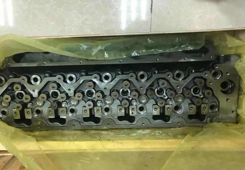
Individual Four-Valve Cylinder Heads
Each cylinder uses an individual four-valve cylinder head. This arrangement supports gas flow and permits cylinder-level head work without treating the entire V12 as one cylinder-head assembly.
Perkins 4000 Series engines share certain design principles and component families, but this does not establish universal interchangeability between 4006, 4008, 4012 and 4016 engines. Every component must be verified against the exact Build List and ESN.
Temperate and Tropical Cooling Packages Are Not the Same Size
The temperate and tropical packages have different dimensions and dry weights. The tropical package uses a larger cooling arrangement for higher ambient-temperature conditions.
| Cooling Package | Dimensions (H × L × W) | Dry Weight |
|---|---|---|
| Temperate | 2269 × 3915 × 2200 mm | 5690 kg |
| Tropical | 2614 × 3919 × 2200 mm | 5860 kg |
The temperate drawing must not be used for a tropical installation. Foundation layout, enclosure height, lifting plan, transport envelope and radiator airflow should all follow the general-arrangement drawing for the approved cooling package.
Cooling Information Required Before Project Release
- Temperate or tropical cooling package
- Maximum site ambient temperature
- Site altitude and expected derating
- Radiator model and fan-drive arrangement
- Cooling-air inlet and hot-air discharge route
- Permitted enclosure pressure restriction
- Coolant specification and expansion arrangement
- Required service access around the radiator and water pumps
Fuel-Oil Cooling Is an Option
Fuel-oil cooling is identified as an available option within the 4012 cooling-package direction. It should not be assumed to be standard equipment.
The supplied page does not provide complete specification data for the fuel-oil cooling option. Confirm the option at inquiry and obtain the applicable piping, cooling and package documents before project release.
| Fuel-Oil Cooling Decision | Information to Confirm |
|---|---|
| Option Status | Optional, not automatically included |
| Application Need | Review fuel temperature, return flow and ambient conditions |
| Package Effect | Confirm additional components, piping and service access |
| Documentation | Applicable option drawing and specification required |
Electro Unit and ElectropaK Are Supply Scopes
The technical specification identifies Electro unit and ElectropaK configurations. These descriptions define engine-package scope and do not automatically represent a complete generator set.
| Supply Description | Scope to Confirm |
|---|---|
| Electro Unit | Included engine accessories, cooling exclusions and applicable drawing |
| ElectropaK | Radiator, fan, filtration, governor, actuator, mounts and included equipment |
| Complete Generator Set | Alternator, base frame, controller, breaker, enclosure and fuel system |
| Replacement Engine Package | Compatibility with the existing alternator, coupling, radiator, exhaust and control panel |
The commercial offer should contain a written inclusion list. Do not assume that the alternator, base frame, enclosure, circuit breaker or external fuel system is included with every ElectropaK.
Installation Engineering for a 1.88 MVA-Class Package
A V12 package in this output class requires foundation, airflow, exhaust, lifting and service-access planning before the engine room or enclosure is released.
| Installation Area | Information to Confirm |
|---|---|
| Foundation | Static load, dynamic considerations, mounting arrangement and levelling |
| Access Route | Door width, roof access, crane capacity and future engine-removal path |
| Cooling Air | Radiator airflow, inlet area, discharge ducting and recirculation risk |
| Exhaust System | Pipe diameter, supports, thermal expansion and permissible back pressure |
| Fuel System | Day tank, transfer arrangement, return line, filtration and fuel quality |
| Alternator Integration | Frame, coupling, alignment, power factor and thermal rating |
| Control Interface | Governor, actuator, sensors, shutdown circuits and genset controller |
| Service Access | Clearance around cylinder heads, injectors, filters, pumps and manifolds |
Alternator Matching
The alternator must be selected for 1500 rpm / 50 Hz operation, the required voltage, power factor, temperature rise, excitation system and transient-load performance.
| Alternator Decision | Information to Confirm |
|---|---|
| Rated Speed | 1500 rpm |
| Frequency | 50 Hz |
| Output Voltage | Project voltage and winding arrangement |
| Power Factor | Confirm the value used for the published kVA output |
| Frame and Coupling | Mechanical interface, alignment and torsional compatibility |
| Temperature Rise | Alternator thermal class and site derating |
| AVR and Excitation | Voltage regulation and transient-load requirements |
Application Review
The 4012-46TAG3A may be evaluated for large prime and standby projects requiring a 50 Hz output in the 1.7–1.88 MVA range. Final sizing should follow actual load behaviour rather than only the total connected load.
| Project Type | Information to Confirm |
|---|---|
| Industrial Facility | Motor starts, compressor demand, process sequencing and permitted interruption |
| Critical Backup Project | Transfer sequence, priority loads, redundancy and expected standby hours |
| Data Centre | UPS interaction, cooling demand, staged transfer and redundancy architecture |
| Large Commercial Facility | Lifts, pumps, ventilation, fire systems and priority-load distribution |
| Infrastructure Project | Pumps, ventilation, communications, safety systems and remote operation |
| Parallel Generator Plant | Synchronization, governor compatibility, protection and load sharing |
Parallel Operation Requires Complete-System Approval
Generator sets using the 4012-46TAG3A may operate in parallel when the complete packages have compatible controllers, alternators, automatic voltage regulators, protection settings, synchronization equipment and governor interfaces.
Parallel capability is not established by the engine model alone. Load sharing, breaker coordination, synchronization sequence and maximum load step must be validated by the genset integrator.
Fuel-Consumption Data Must Be Confirmed Separately
The supplied page does not provide a numerical fuel-consumption table for the confirmed 4012-46TAG3A configuration.
Buyers requiring operating-cost calculations should request specific fuel consumption at defined load points, together with the applicable rating sheet. A litres-per-hour value should not be inferred from the TAG2A or another 4012 model.
| Required Fuel Data | Quotation Requirement |
|---|---|
| Rated Speed | 1500 rpm |
| Duty | Prime, standby or separately approved continuous duty |
| Load Points | 25%, 50%, 75%, 100% and any approved overload point |
| Consumption Unit | g/kWh and litres per hour where available |
| Fuel Specification | Density and fuel standard used for the calculation |
Service Planning
The supplied information states a 500-hour interval for oil and fuel service. The Perkins Operation and Maintenance Manual applicable to the complete Build List and ESN should define the exact tasks, fluids and any adjustments for the operating environment.
| Service Item | Planning Requirement |
|---|---|
| Stated Oil and Fuel Service Interval | 500 operating hours |
| Lubricating-Oil Capacity | 157.5 L (41.6 US gal) |
| Coolant Capacity | 233 L (61.6 US gal) |
| Oil Specification | Confirm from the manual for the exact DGD/DGDM Build List |
| Fuel-System Service | Confirm filters, water separation and fuel-quality requirements |
| Severe Conditions | Review dust, high temperature, fuel quality and prolonged low-load operation |
| Waste-Fluid Handling | Plan collection and disposal for the stated oil and coolant volumes |
Exhaust Aftertreatment and Destination Compliance
Exhaust aftertreatment is listed as N/A in the supplied technical specification. This indicates that no exhaust-aftertreatment system is stated in the listed engine configuration.
It does not confirm compliance with every regional emissions standard. Destination regulations, tender requirements and supporting emissions documentation must be reviewed before quotation or shipment.
Original Perkins Replacement Parts
The following references are listed as original Perkins components for the DGD/DGDM6134 Build List family. Additional Perkins engine parts can be reviewed by component category, but final confirmation should be based on the complete ESN.
| Item | Part Name | Part Number |
|---|---|---|
| 1 | Intake and Exhaust Valve | SE7AJ/14 |
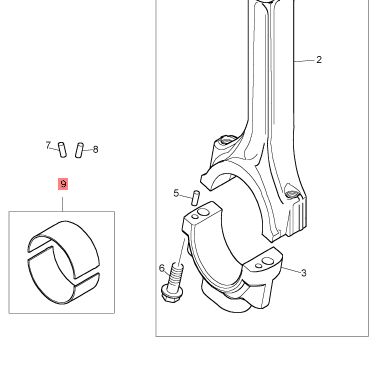
| 2 | Small End Bush | SE91B/7 or Y01/00023 |
| 3 | Valve Guide | T401899 |
| 4 | Valve Spring | 365/472 |
| 5 | Valve Collet | HW7B/18 |
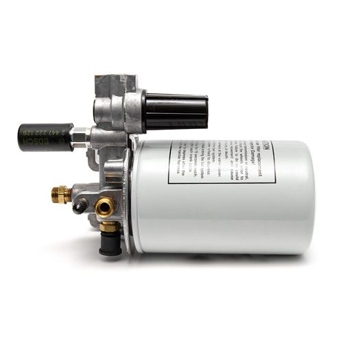
| 6 | Fuel Filter | SE429B/4 or 4759205 |
| 7 | Exhaust Manifold | 12SE15U, 12SE15Y, 12SE15AA, 12SE15W |
| 8 | Air Filter Assembly | SEV551N |
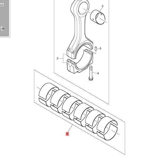
| 9 | Connecting Rod Assembly | SEV91Q |
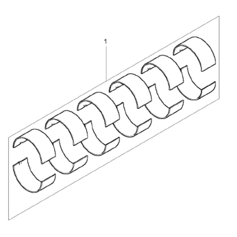
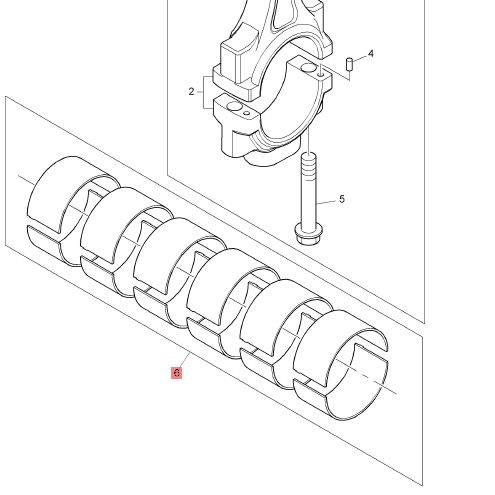
| 10 | Big End Bearing Kit | SE91AA/3M |
| 11 | Piston and Ring Kit | SE901BA |
| 12 | Piston Ring Kit | 359/552 |
| 13 | Starter Motor | 701/137 |
| 14 | Alternator Belt | 541/398 |
| 15 | Injector | 858/35 |
| 16 | Oil Pump | SEV116S or SEV116AC |
| 17 | Oil Filter | 4324909 |
| 18 | Water Pump Kit | SE145AY |
Several components have more than one possible reference. Do not select parts by appearance, dimensions or the general 4012 model name. Confirm the complete DGD/DGDM Build List and ESN before releasing the final part number and quantity.

Procurement and Export Release
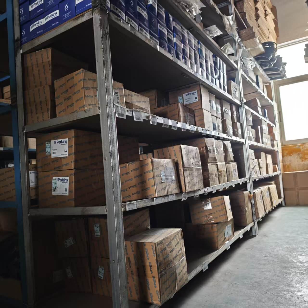
Availability should be confirmed when the inquiry is submitted. The stated lead time is typically 3–4 weeks, and quotations are provided within 24 hours after the configuration, quantity and delivery terms have been defined.
| Procurement Item | Supply Information |
|---|---|
| Supply Source | Genuine Perkins through a first-tier authorised distributor channel |
| Quotation Basis | Build List, ESN, rated speed, cooling package, supply scope, quantity and delivery terms |
| Quotation Time | Within 24 hours after receiving complete inquiry information |
| Typical Lead Time | 3–4 weeks, subject to availability confirmation |
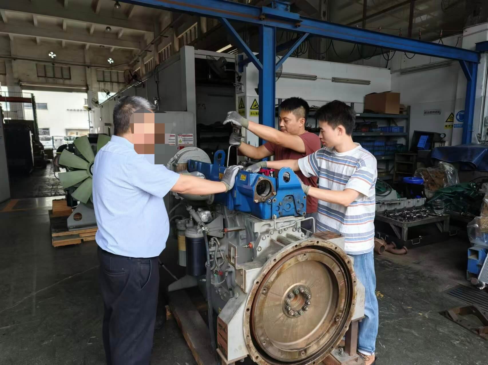
| Pre-Shipment Verification | ESN and engine nameplate checked before dispatch |
| Engine Test Report | Available on request |
| Export Documents | Commercial invoice, packing list, bill of lading and certificate of origin |
| Shipping | FCL or LCL from Shenzhen, Guangzhou or Shanghai |
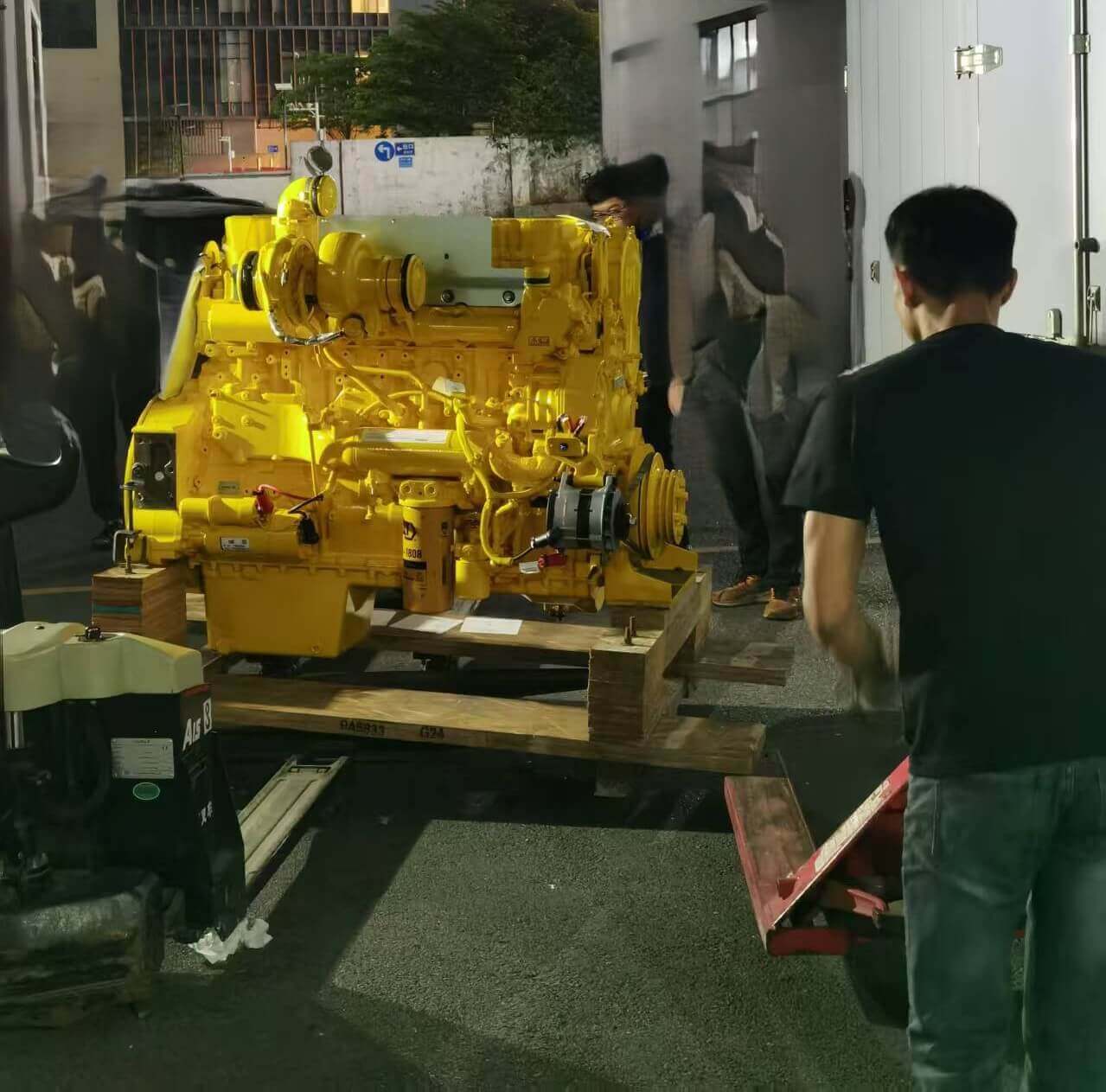
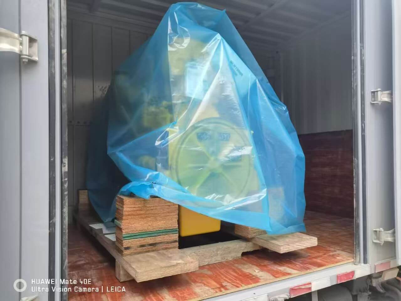
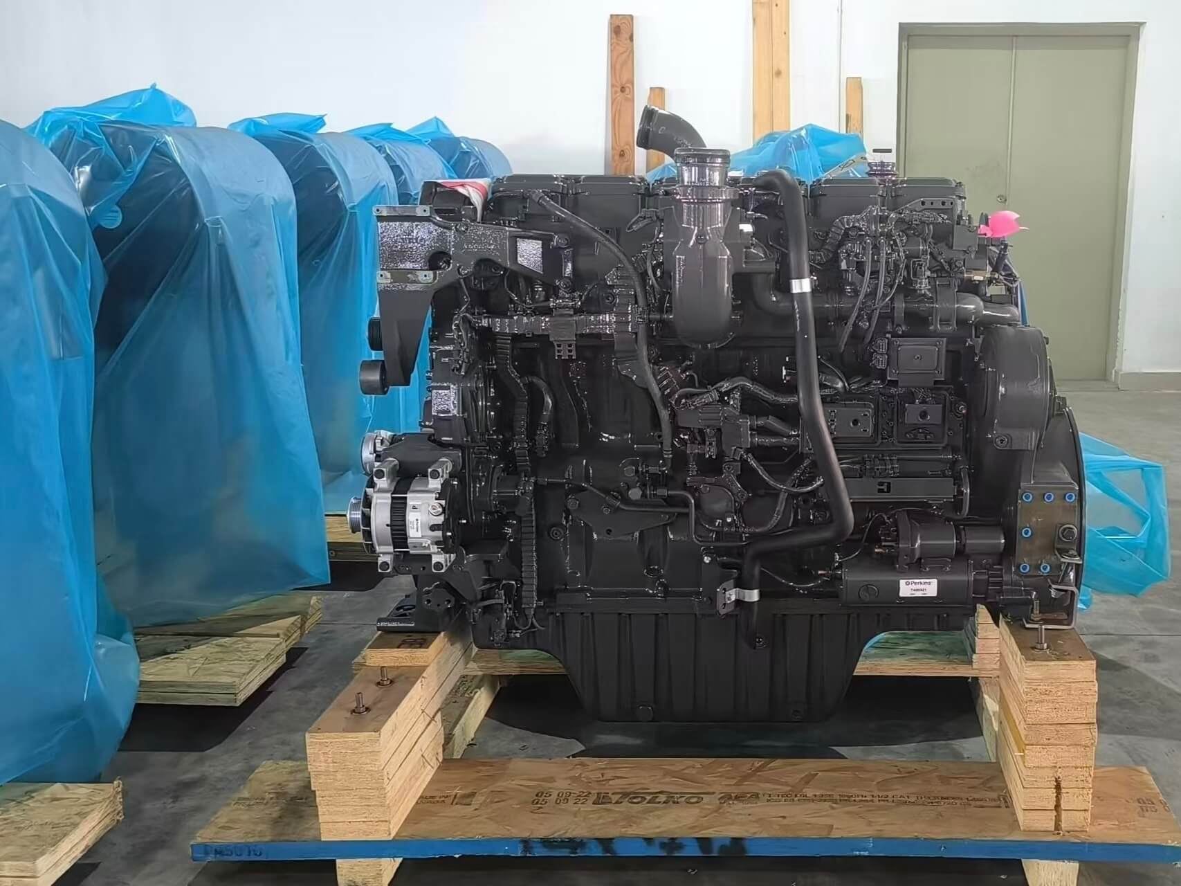
| Packaging | Crating and export packaging included |
| Export Experience | Supplied to more than 30 countries |

Warranty and Technical Claim Review
The stated warranty period is 12 months or the manufacturer-specified operating hours from the commissioning date, whichever occurs first. Final coverage should be confirmed against the engine serial number, operating duty and applicable warranty terms.
Conditions Outside Warranty Coverage
- Incorrect installation or improper commissioning
- Failure to follow the applicable Perkins Operation and Maintenance Manual
- Normal consumption of filters, belts, coolant and lubricants
- Damage caused by contaminated fuel or an incorrect lubricant specification
- Cooling-system neglect
- Unauthorised modifications or repairs during the warranty period
- Transit damage not reported within three working days of delivery
Information Required for Technical Review
- Complete Build List and ESN
- Current operating hours
- Configured rated speed and generator frequency
- Prime or standby application
- Fault description and operating conditions
- Available control-panel alarms
- Photographs and relevant commissioning or service records
The stated technical-review period is within two business days after the required evidence has been received. Depending on the assessment, the response may include replacement parts, coordinated repair support or an engine exchange.
After-Sales Support
- Technical inquiries by email or WhatsApp with a stated one-business-day response direction
- Parts identification for DGD/DGDM6134 builds
- Operation and Maintenance Manual and wiring diagrams available on request
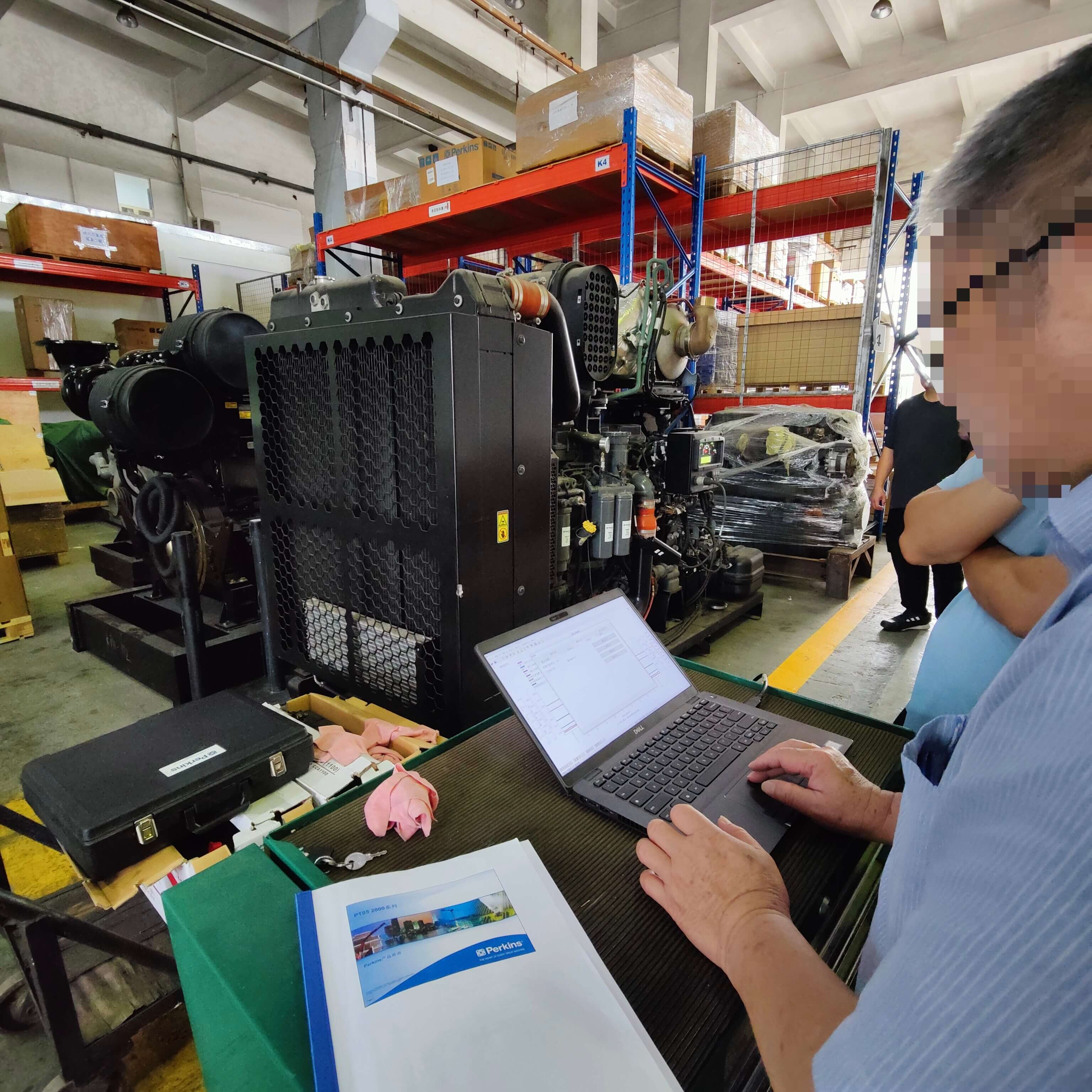
- Remote fault diagnosis by email or video call
Transit Damage Procedure
Inspect the shipment before signing the delivery receipt. Photograph visible damage before unpacking, record it on the receipt and notify the supplier within three working days. Do not commission a visibly damaged engine before the transport-damage report has been reviewed.
Perkins 4012-46TAG3A FAQ
What are the confirmed prime and standby outputs?
At 1500 rpm / 50 Hz, the confirmed outputs are 1710 kVA prime and 1880 kVA standby, corresponding to 1368 kWe and 1504 kWe.
Is 1880 kVA a continuous rating?
No continuous numerical rating is provided in the supplied power table. The 1880 kVA figure is the standby rating.
Which Build Lists carry the confirmed 1710/1880 kVA rating?
The confirmed original Build Lists are DGDM6134, DGDM0083 and DGDM1419. Their shortened versions are DGD6134, DGD0083 and DGD1419.
Can the confirmed 1500 rpm engine be converted to 1800 rpm?
The model designation exists on separate 1800 rpm Build Lists, but those are distinct engine builds. A field conversion should not be approved from the model name alone.
Does the engine use a full engine-mounted ECM?
No full engine ECM is stated. Fuel delivery and speed are managed through unit injection, an actuator and an electronic governor.
How do the temperate and tropical packages differ?
The temperate package is stated at 2269 × 3915 × 2200 mm and 5690 kg. The tropical package is larger at 2614 × 3919 × 2200 mm and 5860 kg.
Is fuel-oil cooling standard equipment?
No. Fuel-oil cooling is identified as an available option. Its inclusion and applicable technical data must be confirmed at inquiry.
What is the stated maintenance interval?
The supplied information states a 500-hour interval for oil and fuel service. Exact tasks and adjustments should follow the applicable Perkins manual.
Does N/A aftertreatment confirm emissions compliance?
No. It indicates that no exhaust-aftertreatment system is stated in the supplied configuration. Destination emissions requirements must still be confirmed.
What information is required for a quotation?
Provide the complete Build List, ESN, rated speed, duty, cooling package, fuel-oil cooling requirement, supply scope, alternator information, quantity, destination and required documents.
Request a 4012-46TAG3A Configuration Review
Submit the following through the engine inquiry and quotation page:
- Complete DGD or DGDM Build List
- Complete ESN or a clear nameplate photograph
- Required rated speed and generator frequency
- Prime, standby or separately reviewed continuous-duty requirement
- Temperate or tropical cooling package
- Fuel-oil cooling requirement
- Electro unit or ElectropaK supply scope
- Governor, actuator and control-panel information
- Alternator model, output voltage and power factor
- Maximum site temperature and altitude
- Original generator-set manufacturer and model for replacement projects
- Quantity, delivery terms and destination port
- Required emissions, export, test and warranty documentation
Related Product
Get Your Engine & Parts Quote
Upload your parts list or send your ESN — we reply within 30 minutes. Engine down? Need fast replacement? Contact us to check today’s stock & delivery time.