

Perkins Camshaft Parts: Lobe Profile & Follower Must Match

2208
Table of Contents
Generating table of contents
A camshaft can slide into the original bearing bores and its gear can mesh correctly with the crankshaft gear—yet it may still be the wrong camshaft.
Camshaft matching has two separate dimensions. Physically, the shaft must be supported, lubricated and located correctly. Kinematically, it must work with the followers and timing system to produce the intended phase relationship.
An error in either dimension can cause valve-train noise, early wear or incorrect valve timing. On engines where the fuel-system drive shares part of the same motion chain, the error may also affect fuel-system drive or timing relationships.
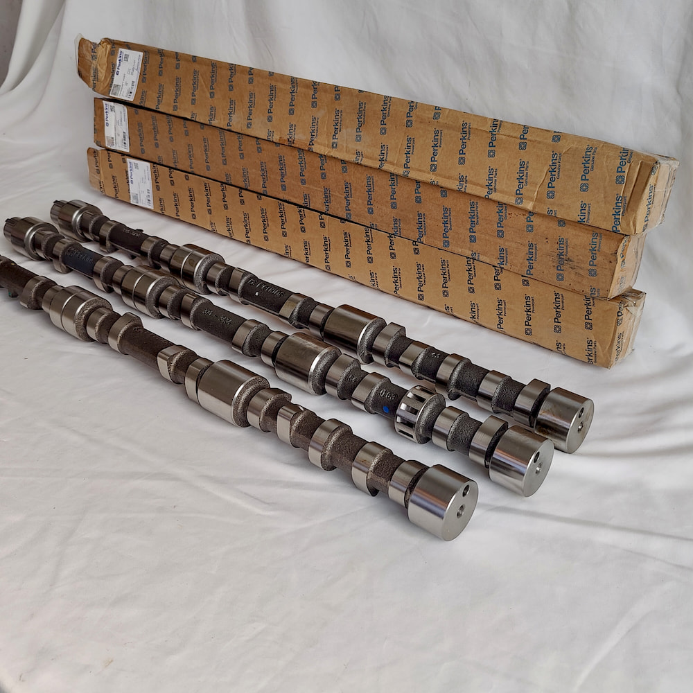
The Same Engine Series May Use More Than One Formal Camshaft Version
An engine model identifies a general platform, but it does not determine one exact camshaft version.
The same engine series may use several formal service versions with different lobe profiles, drive features or locating details. Those differences may relate to engine configuration, fuel-system design, production stage or application. Without the Build List and formal part data, however, they should not be attributed automatically to one specific power rating or emissions level.
Some camshafts do more than control the intake and exhaust valves. Depending on the engine design, an eccentric may drive a mechanical diaphragm-type lift pump, while unit-pump or pump-nozzle systems may use dedicated camshaft lobes as part of the fuel-system drive.
A central injection pump is different. It is normally driven from the crankshaft through a timing gear train, chain or toothed-belt system that may also drive the camshaft. It is not correct to describe every central injection pump as being driven directly by a cam lobe.
The actual drive relationship must be confirmed from the engine design.
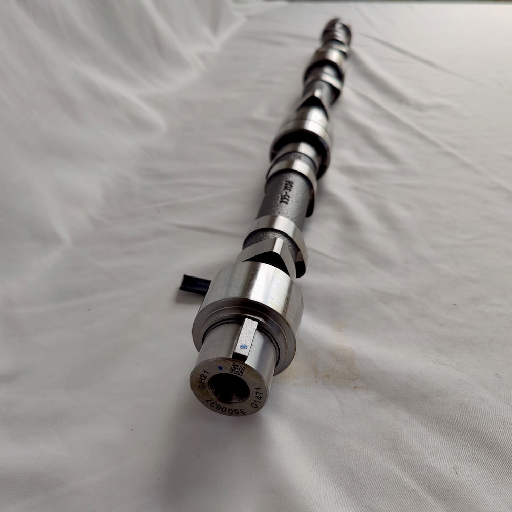
Two camshafts may have similar overall length, journal count and external appearance while using different lobe profiles. Visual similarity is not a reliable matching method. Accurate identification requires the complete Engine Serial Number, Build List and the formal markings on the old component.
The Camshaft Defines the Motion Input, but the Entire Valve Train Defines Actual Valve Motion
The height difference between the cam nose and the base circle provides useful information about lift, but it does not describe the complete lobe profile.
Two lobes may have similar maximum height while using different opening ramps, nose radii or duration. Their resulting valve motion can therefore be different.
Cam lift is also not always equal to final valve lift. In systems using tappets, pushrods and rocker arms, the final motion is influenced by rocker geometry, valve lash and the condition of every component in the motion chain.
The actual valve movement is therefore produced by the complete valve train.
Measuring only the highest point of the cam lobe, without checking the base circle, full profile, follower condition and valve clearance, does not prove that the original valve motion has been restored.
Camshaft Bushes: Oil-Feed Position and Installed Clearance Must Be Confirmed Together
The camshaft rotates on its journals within the engine block or fitted bushings.
On designs using pressure-fed camshaft bushes, the bush oil hole or groove must form the correct connection with the engine-block oil gallery. Different bush positions may use different part numbers, oil-hole patterns or oil-groove designs. The same bush may also require a different installed orientation depending on its position.
Whether a dedicated installation tool is required, and the correct clocking position of the oil hole, must be taken from the service information for the specific engine. A common oil-hole position used on another engine should not be transferred to the current Perkins application.
The press-fit installation process may also change the bush’s final inside diameter, roundness or alignment. Interference fit, accumulated tolerances and material displaced or raised during installation can all alter the actual working clearance.
The free-state inside diameter measured before installation is therefore not a substitute for the installed measurement. On applicable engines, the bush bore, journal clearance and alignment must be checked after installation.
Flat-Faced and Roller Followers Use Different Contact Principles
Flat-faced sliding followers and roller followers are two common valve-train designs, although other motion-transfer arrangements may also be used.
Their contact and guidance principles are fundamentally different, and they must not be interchanged merely because their installation dimensions appear similar.
In many flat-tappet systems, the cam lobe has a very slight transverse taper. The follower face may also have a slight crown, while the follower bore may be offset from the centre of the lobe. Together, these features promote slow follower rotation and distribute wear across the working surface.
The exact taper, crown and offset are design parameters for the specific engine and should not be assigned one universal value.
A roller follower operates differently. The roller rotates around its own shaft and follows the lobe through rolling contact. A guide, anti-rotation pin, keyway or similar mechanism limits rotation of the follower body within its bore so that the roller axis remains correctly aligned with the cam lobe.
The guide does not prevent the roller itself from rotating.
Without explicit approval from the engine or valve-train manufacturer, flat-faced and roller follower systems should not be substituted across types. Their lobe profiles, contact geometry and guidance arrangements use different design logic.
Follower reuse also depends on whether the original or a new camshaft is being installed.
If the original camshaft and its original flat followers have been inspected, accepted for continued service and approved for reassembly, each follower should return to the lobe position with which it originally operated.
When a new camshaft is installed, sliding followers such as flat tappets should normally be renewed in accordance with the applicable service procedure. Returning an old follower to its former cylinder position is not sufficient justification for using it on a new camshaft, because its contact surface has already worn to the profile of the old lobe.
Whether a roller follower may be reused should be determined from the condition of its roller, bearing and guidance mechanism.
Correct Rotation Does Not Prove Correct Axial Location
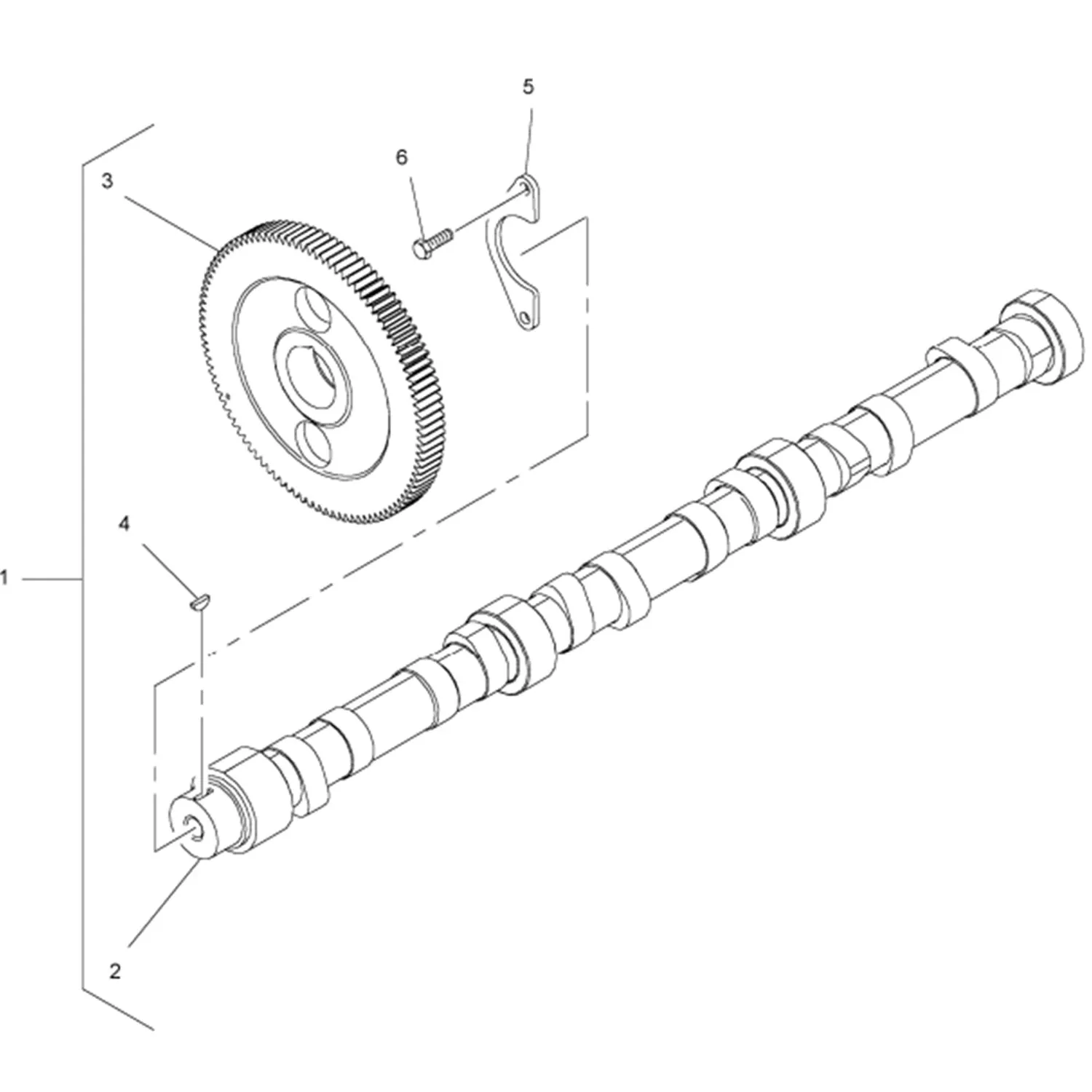
The camshaft must not only rotate; it must also be held within a defined axial position.
A thrust plate, flange, thrust face or another locating structure controls camshaft end float. Excessive end float may allow the camshaft to move forward and backward during operation, affecting gear mesh and follower contact position. Insufficient end float may cause binding, heat generation or thrust-face wear.
After confirming overall shaft length and journal dimensions, the repair process must also verify:
- the location of the axial reference surfaces;
- whether the thrust component is included;
- the condition of the thrust faces;
- the actual assembled end float.
A bare camshaft and a camshaft supplied with a gear may not include the same thrust or locating components. The quotation title does not define the complete bill of materials.
Timing Marks Are Only One Part of the Timing Relationship
Camshaft keyways, locating dowels, gear offset and the formal camshaft-to-gear relationship all determine the actual phase of the camshaft relative to the crankshaft.
An incorrect camshaft or gear version may assemble mechanically and may even appear to align at the visible timing marks while producing valve timing that differs from the original design.
When the same timing gear train also drives a central injection pump, the pump timing must be confirmed separately from camshaft timing.
The applicable procedure may require verification of the injection-pump locking position, pump-gear indexing, number-one cylinder at compression top dead centre and the specified backlash or gear-installation method.
Correct alignment of the camshaft timing marks does not automatically prove that injection timing is also correct.
Valve-Train Noise and Low Oil Pressure Are Separate Diagnostic Paths
Valve-train noise, abnormal valve lash or changes in engine performance may result from the cam lobe, follower, pushrod, rocker arm, valve spring or, on chain- or toothed-belt-driven engines, the condition of the tensioning and guide components.
Sound alone does not prove that the camshaft itself has failed.
Low oil pressure belongs to a separate lubrication-system diagnosis. It should not be explained by valve-spring fatigue or timing-system tensioner problems.
Excessive camshaft-journal or bush clearance may represent one internal oil-leakage path, but a low-pressure reading does not identify the camshaft as the failed component.
During disassembly, useful inspection directions include:
- whether the bush oil holes or engine-block galleries are obstructed;
- whether the lubricant contains abrasive particles or machining debris;
- whether the required assembly lubricant was used;
- whether axial location or gear mesh creates abnormal resistance.
The damage location can help identify where lubrication, contact or positioning first became uncontrolled. It should not lead automatically to the single conclusion that only the camshaft needs replacing.
Comparing New, Remanufactured and Reground Camshafts
Camshaft regrinding may restore or alter a lobe profile by machining the lobe flanks and base circle.
Some processes reduce the base-circle diameter. This can affect valve lash, follower position or pushrod and rocker geometry. Regrinding is therefore not simply a matter of producing a new-looking lobe.
Other formal repair methods may apply material to the lobe before re-machining and restoring the required surface condition. Not every reground camshaft follows the same process.
Camshaft lobes normally use a hardened or surface-treated working layer, but regrinding does not automatically destroy that layer in every case.
The correct questions are:
- what material the camshaft uses;
- how much material was removed or restored;
- the final surface hardness;
- whether a surface-strengthening or heat-treatment process compatible with the camshaft material, original manufacturing method and repair specification was completed.
For industrial engines and generator sets intended to operate to the original calibration, the buyer should confirm that a remanufactured or reground camshaft restores or maintains the lobe profile, base-circle relationship, journal dimensions and surface hardness required by the original service specification.
An unverified performance-oriented regrind should not be treated as a standard replacement camshaft.
Align the Quotation Scope Before Comparing Prices
A “camshaft” quotation may cover only a bare shaft, without bushes, followers or a timing gear. Another quotation may cover a broader repair package.
Before comparing price, confirm:
- whether the quotation is for one bare camshaft or a kit;
- whether camshaft bushes are included, with the part number and oil-hole or oil-groove form for each position clearly identified;
- whether the follower type has been matched to the lobe profile;
- whether the thrust and locating components are included;
- whether the timing gear or sprocket is supplied.
An unclear supply scope can leave additional parts missing even when the camshaft version itself is correct.
Information Required to Define the Camshaft Version
Useful evidence includes:
- complete engine model, Engine Serial Number and Build List;
- the old camshaft’s formal part number, casting marks, forging marks, stamped numbers and other readable identification;
- photographs of the complete camshaft, individual lobes, journals, gear end and thrust surfaces;
- confirmation of the follower type;
- photographs of any related fuel-system drive structure where the camshaft participates in that drive;
- physical findings from disassembly, including journal wear, follower contact condition and cam-bush oil-hole alignment.
When this information is incomplete, a supplier may provide only a budgetary reference rather than a final order confirmation.
ZEB Power’s role in this type of purchase is not to diagnose the complete valve train from symptoms. It is to organise the engine identity, formal camshaft version, follower type and axial-locating structure into a supply scope that can be compared accurately.
Whether the lobe profile remains acceptable, the installed bush clearance is correct and the timing phase meets specification must still be established from measurements and the applicable service information.
Frequently Asked Questions
Can Flat-Faced and Roller Followers Be Interchanged?
Not merely because their installation dimensions are similar. Their lobe-profile design, contact method and guidance logic have fundamental differences. An incorrect combination may produce abnormal valve motion, edge loading or component damage.
Can Old Followers Be Used with a New Camshaft?
When installing a new camshaft, flat tappets and other sliding followers should normally be replaced as specified by the applicable service procedure.
When the original camshaft and original followers are being reassembled, and both have passed inspection and the service procedure permits reuse, each follower should return to its original lobe position.
Whether roller followers can be reused depends on the measured condition of the roller, bearing and guidance mechanism.
Do Correct Camshaft Timing Marks Prove That All Timing Is Correct?
Not necessarily.
If the same timing gear train also drives a central injection pump, the pump locking position, pump-gear indexing and number-one cylinder compression top dead centre must be confirmed separately according to the service procedure.
Does Low Oil Pressure Prove That the Camshaft Is Worn?
No.
Low oil pressure requires investigation of the oil condition, oil pump, pickup system, relief valve, bearing clearances and the wider lubrication system. Excessive cam-bush clearance may be one internal leakage path, but the pressure reading alone cannot prove camshaft failure.
Can a Reground Camshaft Be Used in an Industrial Engine?
It requires careful evaluation.
Confirm that the regrind restores or maintains the lobe profile, base-circle relationship, journal dimensions and surface hardness required by the original service specification, and that any necessary compatible surface treatment or heat treatment has been documented.
Not all reground camshafts are produced to the same process.