

Perkins Oil Pump: Match the Drive, Relief Valve and Supply Scope

2726
Table of Contents
Generating table of contents
When low oil pressure appears, the oil pump is often the first component added to the purchasing list.
However, an oil-pressure reading reflects the combined condition of the entire lubrication system; it is not a direct test of the pump itself. The oil pump provides flow. System pressure is created by the relationship between oil viscosity, engine speed, pressure-fed clearances and flow resistance through the oil galleries and filter, while pressure-relief components limit the upper pressure range.
Flow and pressure are not the same thing. Normal pump flow does not guarantee normal system pressure, and a low pressure reading does not prove that the pump has failed.
Whether an oil pump is serviceable should be judged against its correct service-part version, internal clearances and performance requirements. These are defined standards, not adjustable relative values. What varies is the system result: the engine’s ability to establish the specified oil pressure depends on pump output, oil viscosity, temperature, speed and the amount of internal leakage throughout the lubrication system. A fully serviceable pump can still produce a low system-pressure result when pressure-fed engine clearances have worn beyond their limits.
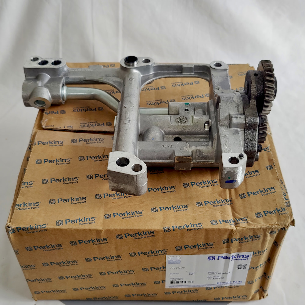
This guide explains the points that are most often overlooked when selecting a Perkins oil pump and investigating abnormal oil pressure.
1. Answer Two Questions Before Replacing the Pump
A low oil-pressure warning does not automatically justify replacing the oil pump.
Low pressure can occur while the pump itself remains serviceable. Possible causes include:
- oil viscosity that is unsuitable for the operating condition, or excessive oil temperature that reduces viscosity;
- air entering through the pickup tube, its connection or a damaged seal;
- a pickup screen restricted by sludge or debris;
- a pressure-relief valve stuck open or unable to close fully, allowing flow to escape too early;
- excessive clearance at main bearings, connecting-rod bearings, camshaft bushes or other pressure-fed lubrication points;
- an incorrect reading from the pressure sensor, wiring or instrument.
A low-pressure warning should therefore lead to two questions.
First, is the displayed pressure genuine, and has it been verified using the specified test method? Second, if the pressure is genuinely low, is the loss occurring at the pickup side, inside the pump, at the pressure-control system or downstream within the engine?
Replacing the pump before separating these possibilities may simply remove a component that was still functioning correctly.
2. Internal Engine Leakage Changes Oil Pressure, but It Should Not Be Hidden with a Larger Pump
As main-bearing, connecting-rod-bearing, camshaft-bush and other pressure-fed clearances wear, oil escapes through those clearances more quickly. The system may therefore show low pressure even when the correct standard oil pump is installed and remains fully serviceable.
In this condition, low pressure indicates that internal engine clearances need to be checked. It does not mean that the engine should be fitted with a higher-volume or higher-pressure pump to compensate.
This distinction matters because increasing pump displacement changes system flow, the operating duty of the pressure-relief system and the pump’s drive load. If the pressure-control system is incompatible, its bypass capacity is insufficient or the oil circuit contains a restriction, abnormal pressure may also result. That does not mean that a larger-displacement pump automatically creates higher pressure; it means that the original balance between flow and pressure control has been altered.
Unless the applicable Perkins service information specifies an approved alternative configuration, pump displacement should not be increased and the relief-valve setting should not be raised to conceal internal wear. When pressure-fed clearances are outside specification, the correct repair direction is to measure and restore those clearances rather than “upgrade” the oil pump.
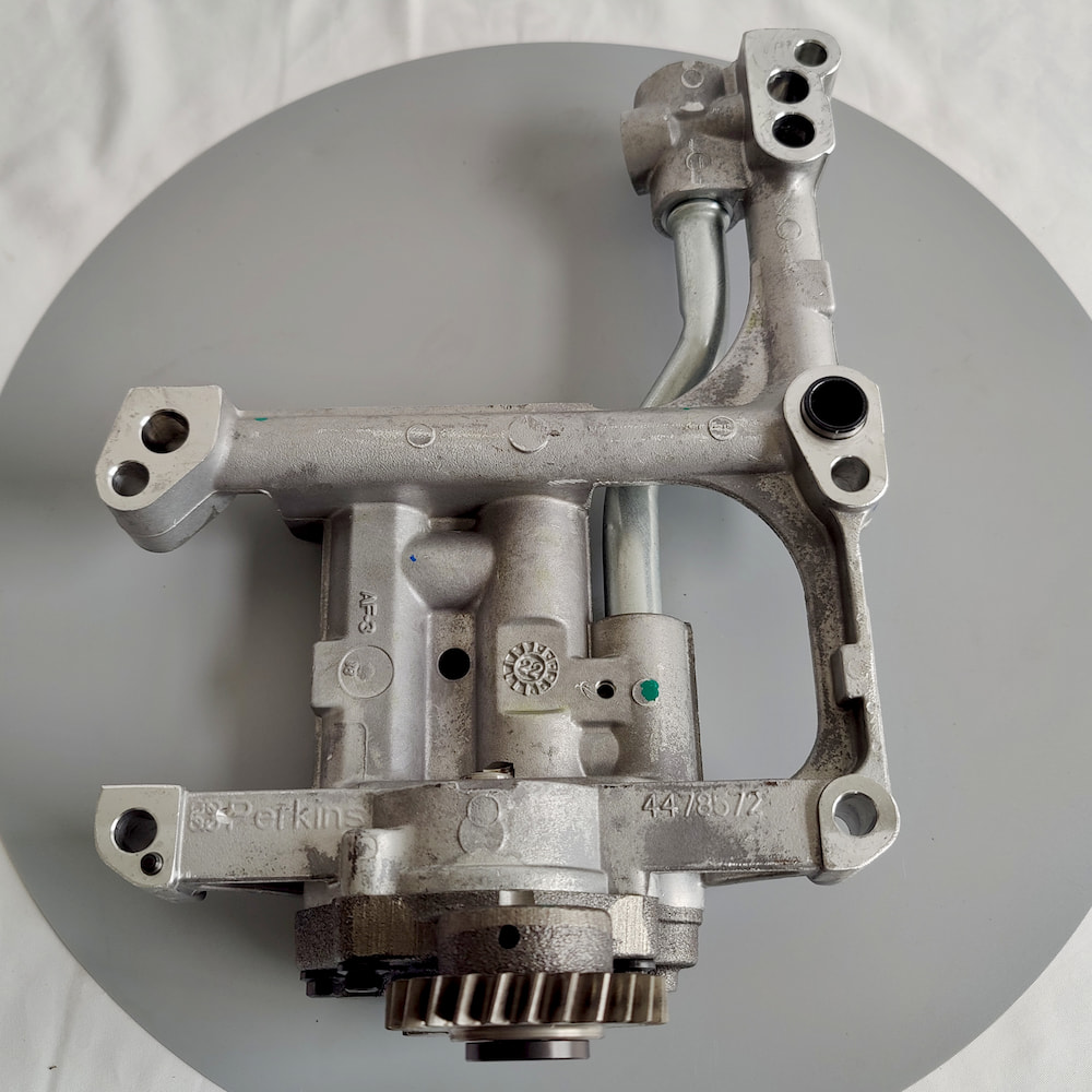
3. The Relief Valve Defines the Pressure Boundary, but It May Not Be Inside the Pump
A positive-displacement pump delivers more oil as its speed increases. To prevent system pressure from rising uncontrollably during cold starts, high-speed operation or high-viscosity conditions, the lubrication system normally uses a pressure-relief valve or another regulating arrangement. This directs part of the flow back to the low-pressure side or into another circuit defined by the engine design.
The regulating component should not automatically be understood as a spring-and-plunger valve built into the oil pump.
Depending on the engine design, the pressure-control function may be located in the pump body, a separate delivery housing, the oil-filter head, an internal block gallery or another lubrication-system component.
There is another common source of confusion. An oil-filter assembly, particularly some spin-on filter designs, may contain a bypass valve or an anti-drain-back valve. These components manage excessive filter pressure differential or retain oil after shutdown. They are not automatically the same as the engine’s main oil-pressure relief valve.
Relief-valve opening behaviour depends on spring force and preload, the valve element’s effective pressure area, and the geometry of the seat and oil circuit. It cannot be reduced to spring preload alone. Products with a similar external form or basic pump housing may still use different pressure-control components and settings for different engine applications, although this must be verified for the exact version rather than treated as a universal Perkins rule.
A valve that remains open or cannot close fully may allow flow to escape too early, making normal pressure difficult to establish. A valve that cannot open as designed may allow abnormally high pressure during cold, high-viscosity or high-speed conditions.
A replacement spring should not be selected by free length alone. Equal free length does not prove equal spring rate, preload or pressure setting.
Before purchasing the pump, confirm whether the relief valve is included. When it is not included, identify where the original engine’s pressure-control component is located.
4. A Drive Mismatch May Allow the Pump to Fit Without Actually Driving It
An engine oil pump may be driven directly from the crankshaft or through timing gears, a chain or another intermediate drive arrangement.
The mounting holes are therefore only one part of the match. The drive side may also require confirmation of:
- drive-gear tooth count and tooth form;
- drive-shaft diameter and length;
- splines, flats, keys or keyway design;
- axial installation depth.
An incorrect drive component can create two very different outcomes.
The first is an obvious no-fit condition, which is normally discovered quickly. The second is more dangerous: the pump housing bolts into place and the drive appears similar, but the engagement depth is insufficient, the drive slips, or the direction of rotation does not correspond to the pump’s internal flow design. The engine may then fail to establish oil flow even though the installed pump looks correct from the outside.
When the old pump is removed, record more than the front housing. The drive end, gear, shaft form and installed depth are also part of the version-identification evidence.
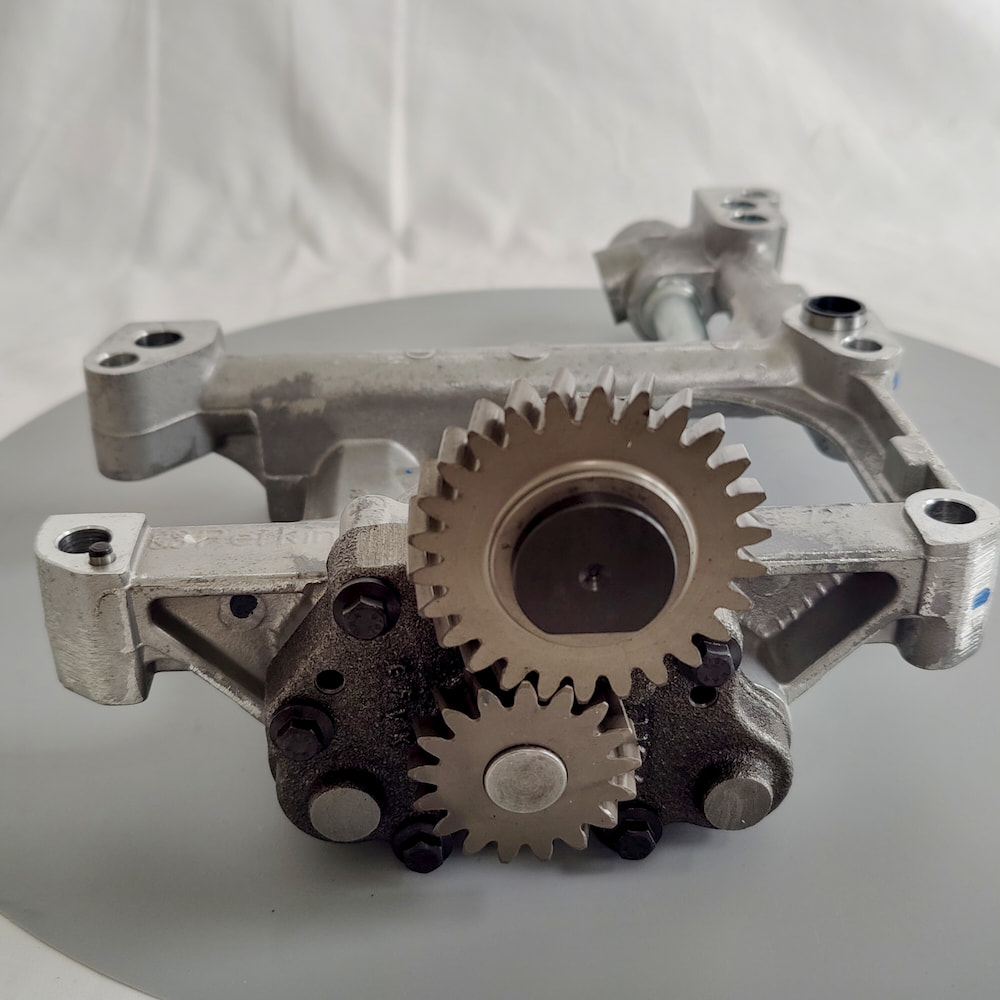
5. Oil-Pump Wear Must Be Measured, Not Judged by Whether the Gears Look Intact
An old pump may have unbroken gears and a freely turning rotor while its working clearances are already outside specification.
The pump relies on relatively small internal clearances to transfer oil from the inlet to the outlet. As the housing, cover, gears, rotors, shaft or bushes wear, part of the oil leaks internally from the high-pressure side back to the low-pressure side. Effective flow falls gradually, and this deterioration is often difficult to judge visually.
The required measurements depend on the pump design. A gear-type pump may require checks of gear end clearance and gear-tip-to-housing clearance. A rotor-type pump may require measurement of inner-to-outer rotor clearance and rotor end clearance.
These dimensions must not be assigned one universal limit across all Perkins engine families. Pumps of similar size may use different materials, designed displacement and allowable clearances.
The housing, cover, gears and rotors also operate as matched working surfaces. Mixing rotors, covers or gears from different used pumps does not automatically create a correctly fitted assembly, even when each individual part appears to be in better condition.
6. A Serviceable Pump Cannot Establish Flow When the Pickup Side Is Wrong
The pickup side must maintain the correct position and sealing condition. A component being bolted into place does not prove that the pump inlet conditions are correct.
The pump must receive a continuous supply of oil from the sump without drawing in excessive air. The pickup tube, screen and connection seals form the inlet system.
If the pickup is too far from the sump floor, it may become exposed during low oil level, equipment inclination or severe oil movement. If it is too close, the surrounding inlet flow area may be restricted. A deformed sump can reduce this clearance further and partially obstruct the pickup.
The specified pickup clearance and installation position must therefore be taken from the relevant engine service information rather than estimated from experience.
Because the pickup side is upstream of the pump, a leak may not create an obvious external oil leak. A damaged seal between the pickup tube and pump can allow air to enter while the engine is running. Oil level and screen condition may appear normal, yet pressure and flow can fluctuate because the pump is receiving an aerated mixture rather than a stable oil supply.
An abnormal pressure-side result does not prove that the failure began on the pressure side. If the pump inlet cannot receive oil reliably, the outlet cannot establish reliable delivery.
7. No Pressure After Installation Does Not Immediately Prove That the New Pump Is Defective
After a new oil pump is installed, the engine must still establish its initial oil supply correctly. This may involve two different procedures that should not be confused.
The first is priming the pump itself. Some dry pumps cannot establish suction quickly and may need to be filled or pre-lubricated with clean engine oil before start-up.
The second applies after an engine overhaul or when the pressure-oil circuit has been completely drained. The engine may require external pre-lubrication of the pressure circuit to remove trapped air and supply downstream lubrication points before normal cranking or start-up.
Pump priming and system pre-lubrication are not the same operation. The permitted medium, connection point and procedure must follow the service information for the specific engine. An unsuitable grease or other unapproved material should not be packed into the oil passages.
When initial oil pressure cannot be established, check in sequence whether:
- the pump itself was primed as required;
- the pressure-oil circuit required and received external pre-lubrication;
- the pickup connection and seal are correctly installed;
- the drive is genuinely engaged;
- the relief valve is assembled correctly;
- the sump oil level is correct.
The engine should not be allowed to run for an extended period with confirmed zero oil pressure in the hope that the pump will eventually “pick up” oil. Initial start-up and pressure confirmation must follow the applicable service procedure.
8. Used and Remanufactured Pumps Cannot Be Valued by Appearance Alone
The most difficult part of evaluating a used oil pump is that the internal clearances controlling its performance are rarely visible in external photographs.
A pump that has been cleaned thoroughly may still have worn end faces, scoring in the housing or enlarged shaft bores. A pump with an ordinary external appearance may still measure within specification.
Descriptions such as:
No cracks
Turns freely
Good condition
only indicate that the housing is not visibly broken and the pump is not obviously seized. They do not prove that its displacement, internal leakage and pressure-control condition remain acceptable.
A remanufactured or rebuilt pump should also be described by the work actually completed. The buyer should know whether gears, rotors, shafts or bushes were replaced, whether the housing was measured, whether end surfaces were restored and whether any flow- or pressure-related test was performed.
The word “remanufactured” alone does not prove that every relevant operation has been completed.
9. Quotation Scope: Pump Body, Pickup, Screen and Drive Components
The term “oil pump” does not describe one fixed supply scope.
Some quotations cover only the pump body, leaving the pickup tube, screen and drive gear to be purchased separately or reused. Other quotations may cover a more complete assembly including the pickup, screen or related housing. The relief valve and drive gear may also be listed separately rather than included automatically.
When reviewing the quotation, confirm exactly which components are supplied, whether the relief valve is included, whether its service-part version and pressure setting correspond to the current engine, and whether the drive-gear tooth count or drive relationship has been matched.
A broad description such as “Perkins oil pump” does not prove that these details have been checked.
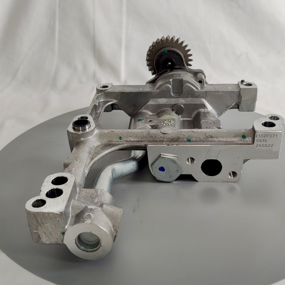
Which Information Helps Separate an Internal Pump Problem from a System Problem?
- engine model, complete Engine Serial Number and Build List;
- the old pump’s service part number, casting marks, stamped numbers and other readable identification;
- photographs of both sides of the pump, the drive end, inlet and outlet ports;
- actual oil-pressure behaviour when cold, when hot and at different engine speeds, together with confirmation of whether the reading was verified by the specified method;
- current oil viscosity, oil level and filter condition;
- whether main-bearing, connecting-rod-bearing or other pressure-fed clearances have been inspected;
- whether the requirement is for the pump body alone or an assembly including the pickup and screen.
The closer the information is to measured and inspected conditions, the faster the supply scope can be defined. When information is incomplete, the engine model may support a budgetary quotation, but low pressure alone should not be used to assume that the quoted oil pump is the final component requiring replacement.
ZEB Power’s role in this type of purchase is not to diagnose low oil pressure as a pump failure on behalf of the repair organisation. Its role is to verify the engine identity, formal pump version, drive and pressure-control interfaces, and the actual supply scope represented by the quotation.
Whether the pressure loss originates inside the pump, at the pickup, in the regulating system or through excessive engine clearances must still be established by physical measurement and the applicable service information.
Frequently Asked Questions
Does Low Oil Pressure Prove That the Oil Pump Is Worn?
No. Pump wear is one possible cause, but pickup-side air leaks or restriction, oil viscosity, relief-valve condition, filter condition and internal engine-bearing clearances can all affect the final reading. These system conditions should be checked separately.
Should a Worn Engine Be Fitted with a Higher-Volume Oil Pump?
Not as a general solution. The pump must first match the engine’s formal service-part version. Unless the service information specifies an approved alternative configuration, increased pump displacement or a higher relief-valve setting should not be used to conceal excessive internal clearances. The correct repair direction is to measure and restore the clearances that are outside specification.
Can Two Oil Pumps Be Interchanged When Their Mounting Holes Match?
Not from the mounting holes alone. Pump displacement, drive interface, inlet and outlet passages, installation depth and pressure-control arrangement may still differ. Confirm the service part number, complete Engine Serial Number and Build List.
Why Is There Still No Oil Pressure After Installing a New Pump?
The pump may not have been primed as required, or the engine may not have received pressure-system pre-lubrication where applicable. Air leakage at the pickup, incomplete drive engagement and incorrect relief-valve assembly can also prevent pressure from being established.
Does a Used Oil Pump That Turns Freely Remain Serviceable?
Not necessarily. Free rotation only shows that the pump is not obviously seized. It does not prove that the working clearances between the gears or rotors, housing and cover remain within specification. Those dimensions must be measured.