

Cummins Oil Pan & Oil Pickup Matching Guide | Avoid Wrong Fit

9051
Table of Contents
Generating table of contents
A Matching Bolt Pattern Does Not Confirm the Correct Configuration
A replacement oil pan may align perfectly with every mounting hole on the cylinder block and still be unusable after installation.
The problem is often not the bolt pattern. The sump position has changed.
The original deep section may have been located at the rear of the engine, while the replacement pan uses a front sump. The existing suction tube may still extend toward the original pickup area, or the new sump may interfere with an axle, crossmember or generator-set base.
An oil pan that bolts to the engine is not necessarily correctly matched to the suction tube, dipstick and available space beneath the equipment.
Oil pans and suction tubes differ from many other engine parts because their shape, depth and internal layout are strongly influenced by the equipment installation. The engine model alone may not define the correct configuration.
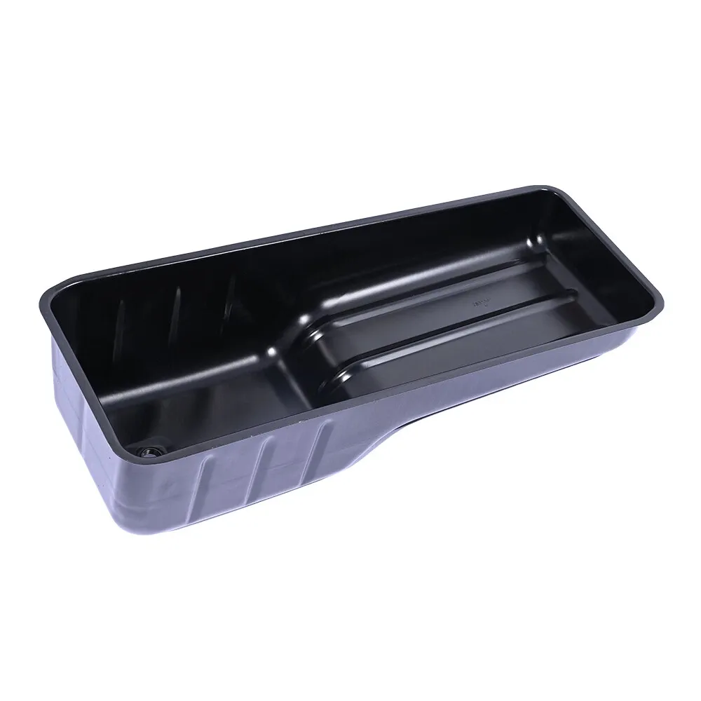
In Cummins parts terminology, what the market commonly calls an Oil Pickup may be identified as a Lubricating Oil Suction Tube, Oil Suction Tube, Oil Suction Connection or another platform-specific service part.
The same Cummins engine may use a different oil-pan capacity or sump position when installed in wheeled equipment, tracked mining machinery or a generator set.
This guide is written for buyers sourcing Cummins oil pans, oil pickups and related parts. It focuses on several matching relationships that are frequently overlooked.
Oil-pressure diagnosis, pickup-clearance measurement and decisions about reusing damaged parts should remain with a qualified repair facility using the applicable service information.
Oil-Pan Shape Is Determined by the Space Under the Equipment
The same Cummins engine model may use a front sump, rear sump or another oil-pan arrangement, depending on the space available around the chassis, axle, crossmember or equipment base.
Terms such as Front Sump and Rear Sump are useful for preliminary descriptions, but they do not complete the identification.
Two pans both described as rear-sump designs may still differ in sump length, offset, lowest external point and drain-plug direction.
If the old oil pan has already been removed, one photograph of it placed upside down on the floor may no longer show the most important installation information.
More useful evidence is normally recorded before removal and shows the pan’s position relative to the axle, crossmember or equipment base, which end of the engine contains the deep sump, and the direction and service access of the drain opening.
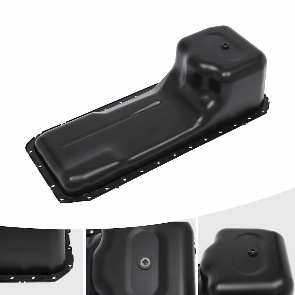
The Oil Pan and Suction Tube Form One Geometric Relationship
A suction tube is not shaped merely to fit somewhere inside the oil pan. It is designed to place the pickup end in a defined oil-collection area.
When replacing the pan, it is not enough to confirm that the pan itself fits the cylinder block.
A pan that mounts correctly to the cylinder block does not prove that the original suction tube can still be used. Conversely, a suction tube that can be installed on the engine does not prove that its pickup end is correctly positioned inside the new pan.
The specified clearance between the pickup end and the bottom of the oil pan must be confirmed from the applicable service information.
It should not be estimated visually, and the suction tube should not be bent, cut or modified simply to make it fit a different sump.
The Dipstick and Gauge Tube Belong to the Oil-Level Configuration
The dipstick, oil gauge tube, oil-pan structure and engine installation position work together as one oil-level indication configuration.
After installing a pan with a different capacity or internal layout, the original dipstick and gauge tube should not automatically be retained.
Even when the old dipstick can still be inserted into the tube, its Full and Low marks may no longer represent the correct oil level for the current configuration.
The dipstick and gauge tube should therefore be checked together with the oil pan and suction tube rather than treated as independent parts.
A Larger Oil Pan Is Not a Simple Upgrade
Some buyers assume that installing a deeper pan and increasing oil capacity must always be beneficial.
Oil-pan capacity, however, is not an independent specification. A change in capacity may also affect suction-tube length and direction, dipstick and gauge-tube configuration, ground clearance and drain access.
Installing only a deeper pan can create a configuration that bolts into place but has an incorrect pickup position, oil-level indication or equipment clearance.
Changing from a standard-capacity pan to a larger version should therefore be treated as a complete configuration change, not simply as the installation of a deeper housing.
Inclined Operation, Impact Damage and Suction-Connection Risk
Some oil-pan and suction-tube configuration problems do not first appear as external oil leaks. They may become noticeable only under a particular operating angle, oil level or operating condition.
Sustained inclined operation: When equipment operates near or beyond the approved inclination for the application, and the oil level, pan and suction-tube configuration are not suitable for that condition, oil movement inside the sump may increase the risk of pickup exposure or unstable oil supply.
Different engines and equipment applications have their own approved installation and operating angles. Suitability for slope, side-slope or sustained inclined operation cannot be determined only from the sump position or the presence of a visible internal baffle.
The applicable limits should be confirmed through the relevant installation manual, QuickServe information or equipment-manufacturer documentation.
Impact damage: An oil pan may be pushed inward without developing an obvious crack or external leak. The deformation can reduce the space between the pickup end and the bottom of the pan.
This type of damage may not immediately leave an external oil trace. A qualified repair facility should determine whether the deformation has affected internal clearance or pickup positioning.
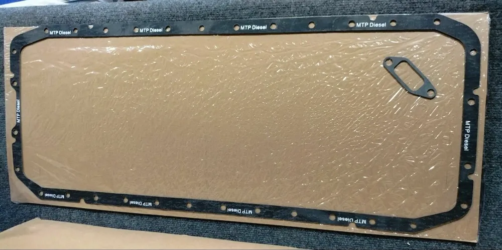
Suction-connection sealing: On engine configurations that use an O-ring, gasket or another sealed suction-tube connection, a failed seal may allow air to enter the suction path without producing an obvious external oil leak.
This may contribute to oil aeration, foaming or abnormal oil-pressure behavior, although these symptoms can also have other causes. The exact connection design and diagnosis must be confirmed from the technical information for the current engine.
The common point is that an external visual inspection may not reveal the complete problem.
If oil-pressure abnormalities or foaming are present, the oil pan, suction tube and suction connections may be included in the inspection, but they should not replace diagnosis of the complete lubrication system.
Transplanted Engines Require Two Separate Checks
When an engine has been transferred from one machine to another—for example, from a vehicle into a generator set—or when its oil pan, suction tube, dipstick or gauge tube has previously been changed, the original ESN configuration may no longer match the equipment currently in service.
The equipment base, axle, crossmember, ground clearance and maintenance access may differ from the engine’s original application.
In this situation, the original ESN configuration should be checked together with the current oil-pan and suction-tube part numbers and photographs of the equipment installation.
The original records help identify the base engine configuration and formal service parts. The current components and installation photographs show what the modified equipment actually requires.
The quotation should state whether the project will restore the original configuration or support the current modified installation.
A Quotation Must Define Both Scope and Installed Configuration
An oil-pan quotation should state whether it includes:
- The oil-pan body;
- The suction tube or related connection;
- The dipstick and gauge tube;
- Gaskets, seals and drain-related parts.
Different suppliers may use the word Assembly for different supply scopes. The complete BOM should not be inferred from the product name alone.
Before ordering, buyers should prepare four groups of information:
Engine identification: ESN, CPL and known part numbers.
Current components: Photographs or part numbers for the oil pan, suction tube, dipstick and gauge tube.
Installation environment: Equipment model, the position of the axle, crossmember or base, and whether the engine has been transplanted.
Purchasing requirements: Quantity, destination and required product condition, such as New Genuine or a confirmed Quality Alternative.
How ZEB Power Supplies Cummins Oil Pans and Suction Parts
ZEB Power separates the quotation into four areas: the oil-pan body, suction-related parts, the dipstick and gauge tube, and sealing or drain-related parts.
Each area is identified as included, supplied separately or expected to be reused from the existing engine.
For transplanted or modified engines, we check the original ESN record and the current equipment installation separately. The product is not confirmed from only one of these references.
ZEB Power can assist with service-part-number verification, supersession checks, product condition and quotation scope.
Oil-pressure diagnosis, pickup-clearance measurement and decisions about reusing damaged components should remain with a qualified repair facility.
Send the engine ESN, CPL, equipment model, and photographs or part numbers for the current oil pan and suction tube. We can help confirm the applicable part numbers and actual supply scope.
Frequently Asked Questions
What must still be checked after the oil pan fits the cylinder block?
Confirm the sump position relative to the equipment structure, suction-tube location, dipstick and gauge-tube configuration, and drain access.
A matching bolt pattern confirms only part of the mounting interface.
How can the original suction tube be approved for reuse?
First confirm that the old and replacement oil pans belong to the same configuration. The repair facility should then verify suction-tube direction, mounting points and pickup-end position.
Do not bend the tube on site to make it fit a different sump.
Which configuration should be quoted after an engine transplant?
Use the ESN to recover the original engine configuration, then use the current oil pan, suction tube and equipment photographs to confirm the installed arrangement.
The quotation should state whether it restores the original configuration or supports the current modified installation.
Which parts are most often missing from an oil-pan quotation?
Check the suction tube or connection, dipstick, gauge tube, seals, drain parts and mounting hardware.
The term Oil Pan Assembly should not be treated as proof of a complete supply scope.