

Perkins Turbocharger Buying Guide: Complete, CHRA or Repair Kit?

1181
Table of Contents
Generating table of contents
A turbocharger can fit perfectly into the original installation position and still be the wrong turbo.
Flanges, ports and brackets determine whether it can be installed. The aerodynamic version, boost-control method, lubrication supply and oil-drain conditions determine whether it can operate as the original engine requires and whether it can achieve a reasonable service life.
Unlike many static mechanical components, turbocharger matching depends heavily on internal aerodynamic characteristics that cannot be seen from the outside and on oil-system conditions that only become critical during operation. External measurements alone are not enough.
From a purchasing and repair perspective, the correct sequence is to confirm the turbocharger version, verify the boost-control system and then check the oil connections and installation orientation. One further issue is often overlooked: damage found on the old turbo may be the result of an upstream engine-system problem rather than the original source of failure.
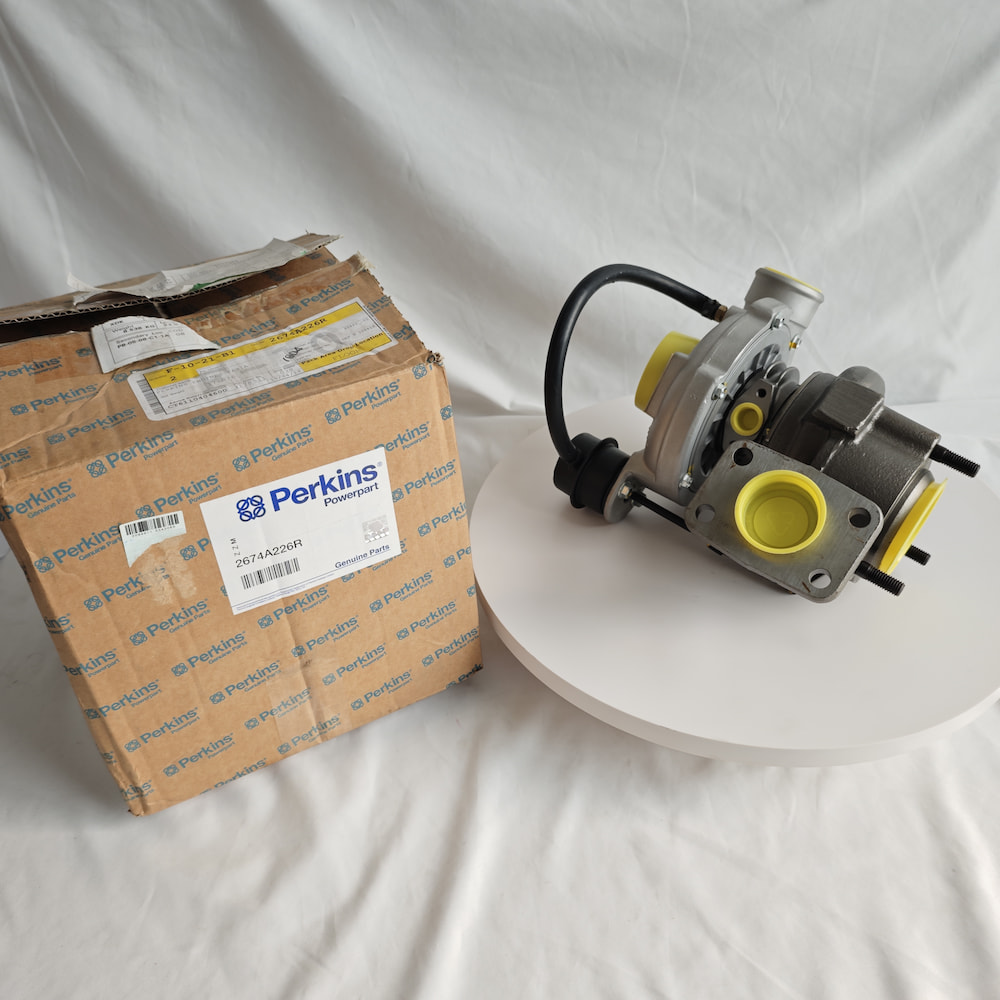
1. Matching Flanges Do Not Prove Matching Aerodynamic Performance
The engine model identifies a general platform, but it does not determine one exact turbocharger version.
The same engine model may use different turbos according to its power rating, emissions configuration, production stage or application. Industrial engines, generator sets, marine equipment and other machinery may have different requirements for transient response, continuous load and exhaust conditions.
Differences between two turbocharger versions may include:
- turbine-housing A/R ratio;
- compressor-wheel and turbine-wheel size and blade design;
- internal compressor- and turbine-housing flow passages;
- wastegate setting;
- housing outlet orientation and installation hardware.
Two turbos may have matching exhaust flanges, compressor inlet and outlet diameters, and mounting holes while using different internal aerodynamic designs. Once installed, their boost response, airflow capacity and exhaust backpressure may still differ from the original engine requirement.
A description such as “Perkins 1104 turbo” should therefore be treated only as a starting search term, not as a final order description. Accurate matching requires the complete Engine Serial Number, Build List, original turbocharger part number and turbo manufacturer’s identification plate rather than the broad engine family alone.
2. Boost-Control Systems Are Not Interchangeable
Perkins engines do not all use the same boost-control architecture.
A fixed-geometry turbo has no wastegate or variable vanes providing active adjustment; its boost characteristics result from the turbo’s aerodynamic design working with the engine’s operating conditions. A wastegated turbo bypasses part of the exhaust flow to limit the energy reaching the turbine. A variable-geometry turbo, often described as VGT or VNT, changes the effective turbine-inlet flow area through an adjustable vane mechanism.
The system used on a particular engine must be confirmed from the formal part data and engine identity. It should not be inferred from the engine’s age or the turbo’s external appearance.
For a diaphragm-style wastegate actuator driven by a positive boost-pressure signal, control pressure and internal spring force determine when the linkage begins to move. Once pressure reaches the corresponding range, the rod starts to travel and progressively opens the bypass valve.
The actuator’s opening characteristic, spring preload, effective travel and rod position belong to the specific turbocharger calibration. Two actuators may have similar housings, mounting flanges, rod lengths and total travel without having the same boost setting.
Whether an actuator can be repaired, whether its rod is adjustable and what calibration is required after adjustment must follow the turbo manufacturer’s or engine service procedure. Boost settings should not be altered by casually changing rod length or spring preload. An old actuator should not be transferred to a replacement turbo simply because the mounting holes align; it must correspond to the same turbo version and calibration relationship.
Variable-geometry systems are more complex. Their actuators may be electronic, pneumatic or vacuum operated. Even among electronic actuators, replacement procedures vary considerably. Some actuators are precisely matched to a specific turbo at the factory and require diagnostic calibration after replacement. Some perform an automatic learning process at first power-up. Other designs do not permit actuator-only replacement and require a complete pre-calibrated turbocharger assembly.
It is therefore inaccurate to state that every replacement VGT actuator “normally requires relearning.” The correct procedure depends on the specific product design and must follow the applicable service information.
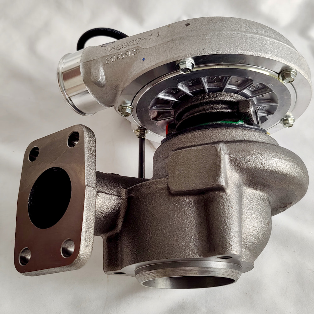
3. Oil Connections and Installation Orientation Determine Whether the Turbo Can Operate Reliably
On some Perkins applications, the turbocharger rotor may reach or exceed 100,000 rpm. Its bearing system depends on a continuous supply of clean, unrestricted lubricating oil to maintain the oil film between high-speed rotating components and stationary surfaces.
Incorrect oil supply, oil drainage or installation orientation can damage a new turbo in a very short period.
Whether the oil-feed connection requires a restrictor must be confirmed from the exact turbocharger part number and the original oil-supply arrangement. A restrictor used on another visually similar turbo should not be transferred automatically, and an original restriction should not be removed without technical justification.
Incorrect oil delivery can prevent the bearing oil film from forming correctly and may cause premature bearing and rotor damage. The turbo should also be pre-lubricated in accordance with the installation procedure. This normally includes adding clean new engine oil through the oil inlet and establishing oil supply before the engine is allowed to run normally, reducing the risk of dry operation during initial start-up.
The oil-drain side involves two separate orientation requirements:
- the rotor axis normally needs to remain approximately horizontal;
- the oil-drain outlet should point downward in the direction of gravity.
These are independent requirements. Satisfying one does not prove that the installation is correct.
If the drain orientation or pipe layout is unsuitable, oil may collect in the center housing and appear as leakage into the compressor or turbine side, leading to oil consumption or blue exhaust smoke. The drain line should also:
- maintain a continuous downward route without low points that retain oil;
- avoid kinks and internal obstruction;
- use the pipe diameter and connection arrangement specified for the original installation.
The permitted angle, line size and routing should be taken from the original turbocharger and engine installation specification rather than from one universal angle rule.
4. Housing Orientation and Water-Cooling Connections Are Version Information
The outlet orientation of the compressor and turbine housings affects the connection between the compressor outlet and charge-air pipework, the air cleaner and compressor inlet, and the turbine outlet and exhaust system. It also affects actuator brackets and linkage, heat shields and available installation space.
Housing direction is therefore not merely a cosmetic difference.
Some turbochargers allow the compressor or turbine housing to be rotated according to a defined procedure, but this is not a universal feature. On a turbo with a wastegate, electronic actuator or variable-geometry mechanism, changing the housing position may also affect linkage geometry, oil-drain orientation or the original calibration.
The housing or actuator position should not be changed simply to make the pipework fit.
Water-cooling connections apply only to turbochargers designed with a water-cooled center housing. On these units, engine coolant connections are used alongside the oil-feed and drain ports to help control center-housing temperature and heat soak after engine shutdown.
If the original turbo has coolant connections and the proposed replacement does not—or the engine has no corresponding coolant circuit but the proposed turbo does—the units may not be the same version. The number, position and specification of the coolant ports, together with the intended coolant-flow arrangement, should be checked.
For identification, multi-angle photographs of the following areas are particularly useful:
- compressor inlet and outlet, and turbine inlet and outlet;
- oil-feed and oil-drain connections;
- actuator, bracket and linkage;
- identification plate and all visible numbers.
These details provide more reliable version evidence than a general statement that the engine model is the same.
5. Damage to the Old Turbo May Not Be the Starting Point of the Failure
Damaged wheels, bearing wear and abnormal axial movement prove that the turbocharger has been damaged, but they do not necessarily show where the failure began.
Possible upstream causes include oil-feed restriction or carbon deposits, contaminated oil, restricted drainage, excessive crankcase pressure, breather-system faults, foreign-object entry from the intake or exhaust side, abnormal exhaust temperature or failure to pre-lubricate the turbo correctly.
This does not mean that the turbo itself cannot fail. Material defects, assembly problems, actuator failure, normal wear and poor-quality replacement products can also be genuine failure sources.
In turbocharger failure analysis, insufficient oil supply, oil contamination, foreign-object damage, drainage problems and external engine conditions are all important upstream areas to investigate. Published sources do not assign the same percentage to each cause, so one failure-rate figure should not be presented as a universal rule for every Perkins application.
Oil leakage is a useful example. Oil found on the compressor or turbine side is often interpreted immediately as an internal turbo sealing failure. In reality, turbocharger oil control also depends on the drain system, intake and exhaust pressure relationships, and crankcase pressure.
A blocked or kinked drain, incorrect drain orientation, excessive crankcase pressure, a faulty breather, severe engine blow-by, or intake restriction can all make oil appear at one side of the turbo. The inspection should therefore establish where the oil is appearing, whether the drain remains continuously open, whether crankcase ventilation is functioning, and whether engine oil pressure and oil level are normal.
The useful purchasing conclusion is:
The old turbo’s damage pattern should determine which systems are inspected next, rather than automatically reducing the repair scope to “replace the turbo.”
If the old unit failed because of oil starvation or contamination, installing a new turbo without addressing the feed line, drain line, engine oil, filters and contamination source may reproduce the same failure within a short period.
6. Align the Quotation Scope: Complete Turbo, CHRA or Repair Kit
The term “turbocharger” does not define one supply scope.
- A Complete Turbocharger Assembly normally includes the compressor housing, turbine housing, center housing, rotating assembly and, where applicable, the wastegate or actuator. The supplier should release the assembly according to its stated assembly, balancing, calibration and inspection standard, while the quotation should still identify the product condition and actual test scope.
- A CHRA, or Center Housing Rotating Assembly, contains the center housing and rotating components. It normally excludes the original compressor housing, turbine housing, wastegate and actuator. Before purchase, the buyer should confirm that the CHRA corresponds to the correct turbo version and has already completed the manufacturer’s required core-assembly balancing and inspection. It should not be treated as an unfinished unit that must be dismantled and rebalanced after delivery.
- A Repair Kit can vary widely. It may contain bearings, sealing rings and fasteners, or it may cover an actuator, compressor or another specific repair area. Where the repair involves dismantling or rebuilding the rotor system, the repair organisation must also have the necessary balancing and high-speed testing capability.
Replacing the CHRA does not correct an incorrect wastegate setting, a distorted compressor housing, a cracked turbine housing, an incompatible actuator or a misadjusted actuator linkage.
Before choosing a supply level, the workshop should inspect the condition of the old housings, actuator, linkage and interfaces. The quotations should then be compared for actuator inclusion, gaskets and seals, oil-line accessories, product condition—such as New, Remanufactured or Used—and any Core Return requirement.
7. Rotor Balance Matters, but It Is Not the Only Factor Governing Turbo Life
Turbocharger rotors operate at very high speed, so even a small imbalance can increase vibration and bearing load. Rotor-assembly balance is therefore an important factor in turbocharger reliability.
It is not the only one.
Turbo life also depends on oil quality, oil drainage, housing condition, boost control, installation cleanliness and the engine’s operating environment. Balance alone cannot establish the overall quality of a turbocharger.
New, Remanufactured and Replacement products should not be compared by description alone.
A new genuine unit normally offers a clearer source and version record, although cost and lead time may be higher. When evaluating a remanufactured turbo, the buyer should establish who performed the work, which internal components were replaced, whether the original housings were reused, whether the actuator was recalibrated, and whether core-assembly balancing and performance testing were completed.
Exchange arrangements may also require the old unit to be returned. Core deposits, return deadlines and acceptance conditions can all affect the final cost.
A validated replacement product can also be a reasonable option, provided the supplier can explain the manufacturing source, part-number relationship and actual testing scope.
Which Information Actually Narrows the Turbocharger Version?
- engine model, complete Engine Serial Number and Build List;
- original turbocharger part number and manufacturer’s identification number;
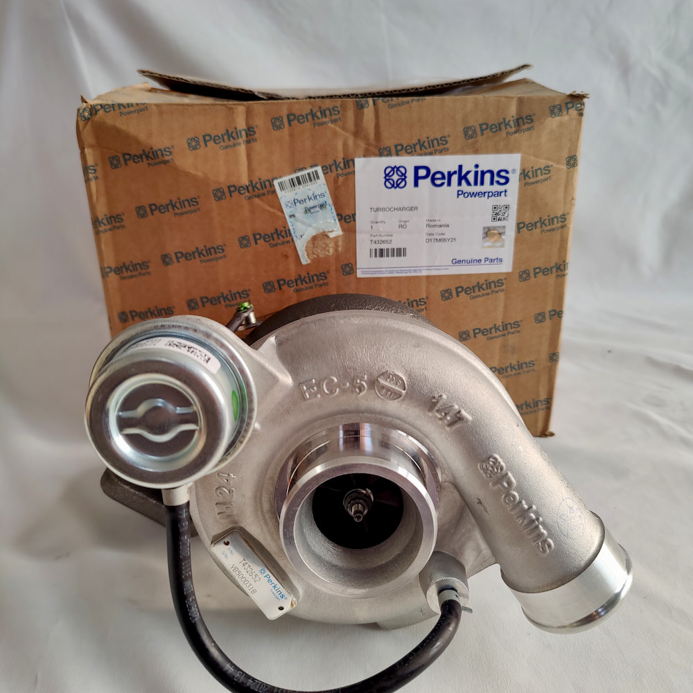
- multi-angle photographs of the complete turbo, compressor side, turbine side, oil connections and actuator;
- current application and engine power configuration;
- the old turbo’s damage pattern and any completed checks of the oil feed, oil drain, crankcase ventilation and intake system;
- the required supply level: Complete Turbo, CHRA or Repair Kit;
- preferred product condition: New, Remanufactured or Replacement.
The closer the information is to measured and inspected conditions, the faster the correct supply scope can be defined. When the available data is incomplete, the engine model and old turbo number may support a budget quotation, but that quotation should not be treated as final confirmation. Until the turbo version, boost-control method and oil-system requirements have been verified, a quoted unit cannot be assumed to be the correct one merely because it will fit.
ZEB Power’s role in this purchasing process is not to replace the repair organisation’s failure diagnosis. It is to convert the engine identity, old-unit numbers, boost-control architecture, housing orientation and product condition into purchasing conditions that can be compared consistently.
For a Complete Turbo, CHRA or Repair Kit, the quotation should also state which balancing, calibration and testing procedures have already been completed. The root cause of the old turbo’s failure, cleaning of the oil-feed and drain system, actuator setup and on-engine installation must still be handled by a repair organisation with the appropriate equipment and service information.
Frequently Asked Questions
Are Turbochargers Interchangeable When the Engine Model Is the Same?
Not automatically. The same engine model may use different turbocharger versions according to power rating, emissions configuration or application. Confirm the complete Engine Serial Number, Build List and old turbo identification.
Can Two Turbos Be Interchanged When Their Flanges and Port Sizes Match?
Not automatically. Compressor and turbine wheels, housing flow passages and boost-control systems may be different. Matching external interfaces prove only that the mechanical installation is similar; they do not prove matching aerodynamic performance.
Can Wastegate Actuators Be Interchanged When Their Housings Look the Same?
Not from appearance alone. The control method, opening characteristic, spring preload and formal part relationship must also correspond.
Does Oil Around the Turbo Always Mean Its Internal Sealing Components Have Failed?
No. Restricted drainage, excessive crankcase pressure, breather faults, intake restriction or incorrect installation orientation can also make oil appear at the compressor or turbine side. These conditions should be checked before the failure is assigned to the turbo itself.
What Is the Difference Between a CHRA and a Complete Turbocharger?
A CHRA normally contains only the center housing and rotating core. It does not usually include the compressor housing, turbine housing, wastegate or actuator. Before purchase, confirm that it corresponds to the correct turbo version and has completed the required core-assembly balancing and inspection.