

Cummins Flywheel & Housing for Sale | SAE, Ring Gear & Interface Matching

7695
Table of Contents
Generating table of contents
The most commonly overlooked issue when sourcing a flywheel is not whether it can be bolted to the crankshaft. Most buyers already know to check that. The more important question is whether the flywheel can work with the complete output-end system behind the engine.
A flywheel may fit the crankshaft and still fail to match the starter motor, clutch, transmission, main alternator coupling, marine gearbox, industrial driven equipment or flywheel housing.
These are related but separate matching layers. None of them should be considered confirmed simply because the flywheel can be installed on the crankshaft.
An engine may be fully assembled and run correctly on a test stand, yet still be unusable at the final assembly site if the flywheel housing SAE size does not match the driven equipment, or if the ring gear, starter and output connection components do not belong to the same configuration. Problems of this kind are often discovered only when the engine is being connected to the transmission, generator end or other equipment, when the cost of rework is much higher than the cost of a complete parts check during procurement.
This guide is intended for:
- Parts wholesalers and importers sourcing Cummins flywheels and flywheel housings for resale;
- Repair companies performing engine overhaul and remanufacturing work;
- Engineers matching engines to vehicles, generator sets, marine gearboxes or industrial equipment;
- Engine rebuilders and equipment service companies evaluating new supply channels.
The applications covered include on-highway vehicles, construction equipment, mining machinery, generator sets, marine engines and industrial power systems.
First distinguish the flywheel, flexplate, drive plate and flywheel housing
Several names commonly appear in inquiries:
- Flywheel;
- Flexplate;
- Drive plate or drive disc;
- Flywheel housing;
- Flywheel assembly;
- Flywheel housing assembly.
These terms are not interchangeable.
Flywheel
A flywheel is installed at the rear of the crankshaft. Depending on the application, it may:
- Store rotational inertia and help stabilize engine rotation;
- Carry the ring gear used by the starter motor;
- Connect to a mechanical clutch;
- Connect to a transmission;
- Connect to a generator coupling or drive disc;
- Connect to another output-end component.
Its exact function depends on the engine application and output configuration.
Flexplate
A flexplate is a relatively thin, flexible output connection component, commonly used with a torque converter or another specific transmission system.
A flexplate and a conventional clutch flywheel may differ completely in:
- Material and thickness;
- Crankshaft mounting pattern;
- Ring gear design;
- Torque-converter or output mounting holes;
- Axial offset;
- Stiffness and flex characteristics.
Some market literature uses the term drive plate broadly for a flexplate. In generator, industrial and marine applications, however, a drive plate or drive disc may refer to a different type of output connection component. The official part name, part number and bill of materials should therefore be checked instead of assuming that every drive plate is a flexplate.
Drive plate or drive disc
In generator, industrial and marine applications, a drive plate, drive disc, coupling plate or similar component may connect the engine flywheel to the main alternator, marine gearbox or other driven equipment.
It may be used together with the flywheel or form part of a separate equipment-manufacturer connection system. Whether it is included with the engine, alternator or driven equipment must be confirmed from the applicable BOM.
Flywheel housing
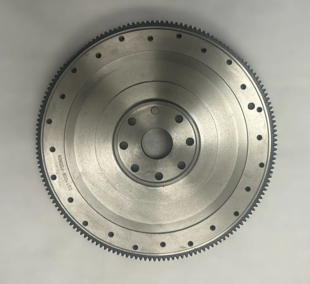
The flywheel housing is installed at the rear of the engine and provides the mounting interface between the engine and a transmission, main alternator, marine gearbox or other driven equipment.
Depending on the design, it may also provide:
- The driven-equipment mounting face;
- The starter mounting pad;
- Clearance around the flywheel and ring gear;
- Inspection openings and protective covers;
- Sensor or pickup mounting points;
- Rear support or accessory mounting features.
A flywheel that fits the crankshaft is not automatically suitable for the existing flywheel housing. The flywheel and housing must be checked separately.
SAE size: the flywheel and flywheel housing use separate specifications
The SAE flywheel housing size standardizes the basic mounting interface between an engine and a transmission, main alternator or other driven equipment.
The housing size normally relates to features such as:
- Housing register or pilot diameter;
- Housing bolt circle;
- Number and arrangement of mounting holes;
- Associated mounting-face dimensions.
Using the same SAE housing size on the engine side and the driven-equipment side is an important prerequisite for mechanical connection, but it does not prove that the complete system can be installed directly.
The following still need to be checked:
- Flywheel SAE size;
- Flywheel axial position;
- Drive disc or coupling;
- Pilot interface;
- Starter mounting-pad position;
- Driven-equipment manufacturer requirements;
- Any adapter housing or spacer between the engine and equipment.
The flywheel may also have its own SAE flywheel size, which describes a standardized connection interface between the flywheel and a coupling, drive disc or other output component.
Flywheel SAE size and flywheel housing SAE size must be confirmed independently.
The following are also separate matching points:
- Pilot bore;
- Pilot bearing or pilot bushing;
- Flywheel thickness;
- Flywheel mounting-face position;
- Drive-disc or coupling mounting holes;
- Axial relationship between the flywheel and housing.
Knowing the flywheel housing SAE number does not confirm every flywheel dimension.
Likewise, a correctly sized flywheel does not prove that the housing will match the existing transmission, main alternator or industrial equipment.
The flywheel and housing fitted to a specific Cummins engine may vary with the engine model, CPL, rating, speed and application. They should not be selected by displacement or engine family alone.
Before ordering, confirm:
- Flywheel SAE size;
- Flywheel housing SAE size;
- Whether the flywheel and housing belong to the same configuration;
- SAE interface required by the driven equipment;
- Drive-disc or coupling configuration;
- Starter mounting location;
- Whether an equipment-manufacturer-specific adapter is used.
Physical measurements can support identification, but final confirmation should still be based primarily on the service part number, ESN/CPL and driven-equipment interface information.
Crankshaft flange interface: confirm that the flywheel fits the current crankshaft
The first level of flywheel matching is the rear crankshaft flange.
Confirm:
- Rear crankshaft flange diameter;
- Center register or pilot diameter;
- Flywheel center bore;
- Number of bolt holes;
- Bolt circle;
- Bolt-hole diameter;
- Number and position of dowel pins;
- Flywheel installation direction;
- Flywheel axial position relative to the crankshaft.
Two flywheels may have the same number of bolt holes and still be incompatible because of differences in:
- Bolt circle;
- Center register diameter;
- Dowel location;
- Asymmetrical bolt-hole pattern;
- Front and rear face design;
- Crankshaft rear-end design version.
If the crankshaft has previously been replaced, provide the current crankshaft part number.
The flywheel originally listed against the ESN may not automatically match a different crankshaft version installed during an earlier repair. The current crankshaft number, flywheel number, ESN/CPL and repair history should be checked together.
Ring gear: match tooth count, tooth form, engagement side and starter system
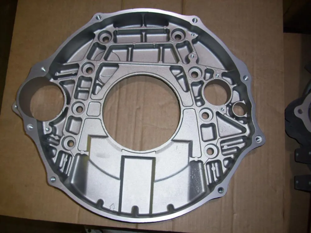
The flywheel ring gear is installed around the outside of the flywheel and engages the starter pinion during cranking.
Tooth count alone is not enough for identification.
Tooth count and tooth form
Confirm:
- Ring gear part number;
- Number of teeth;
- Tooth form;
- Pitch or module system;
- Outside diameter;
- Tooth width;
- Installed position on the flywheel;
- Compatibility with the starter pinion.
Even when tooth count is the same, a different tooth form, diameter or axial position can prevent correct engagement.
Engagement side and axial position
Some ring gears or tooth designs may have a specific:
- Engagement side;
- Lead-in chamfer;
- Installation direction;
- Starter-pinion contact position.
The following therefore need to be checked together:
- Starter installation side;
- Starter-pinion extension direction;
- Ring gear axial position;
- Starter mounting-pad position;
- Internal flywheel-housing clearance.
Matching tooth count cannot replace these interface checks.
Ring gear installation design
A ring gear may use:
- Interference or shrink fit;
- Bolted attachment;
- Another approved installation design.
The installation method, whether the ring gear can be replaced separately and whether an old ring gear may be transferred should be confirmed from the applicable parts and service information, not from appearance alone.
Before ordering, confirm:
- Whether the ring gear is included in the flywheel quotation;
- Whether it is already installed;
- Whether it is supplied loose;
- Whether the old ring gear must be transferred;
- Whether it must be ordered separately;
- Starter motor part number;
- Starter pinion configuration.
If the engine has hard starting, tooth damage or starter grinding, a remote description alone cannot prove whether the problem is the flywheel, ring gear or starter motor. The system should be inspected by a qualified repair facility.
This guide does not provide ring gear heating procedures, engagement clearances or starter adjustment specifications.
Mechanical clutch applications: check the friction face and pilot interface separately
For a flywheel used with a mechanical clutch, the following must be checked in addition to the crankshaft interface and ring gear:
- Flywheel friction-face diameter;
- Clutch-disc diameter;
- Pressure-plate bolt pattern;
- Pressure-plate locating step;
- Flywheel step or other friction-face design;
- Pilot bore;
- Pilot bearing or pilot bushing;
- Flywheel thickness;
- Clutch-housing clearance;
- Transmission input-shaft interface.
A flywheel that fits the same engine does not necessarily fit the same clutch.
The same engine may be installed in different vehicles or equipment, and different OEMs may use different:
- Clutch diameters;
- Pressure plates;
- Transmissions;
- Input shafts;
- Pilot bearings;
- Clutch housings.
The vehicle or equipment model, clutch and transmission information are therefore as important as the engine model when sourcing the flywheel.
If the friction surface has already been machined, whether the flywheel remains usable and whether sufficient machining allowance remains must be determined by a repair facility using the applicable service information.
This guide does not provide friction-surface machining dimensions, flywheel-step specifications or reuse limits.
Generator-set applications: distinguish the charging alternator from the main alternator
In generator-set applications, two different components are often confused:
- The engine-mounted charging alternator;
- The main alternator that generates AC output for the generator set.
The charging alternator charges the starting battery and supplies the engine electrical system.
The main alternator is the principal power-generating component of the genset. The engine output-end flywheel and housing normally connect to the main alternator or its coupling system.
When sourcing a flywheel or flywheel housing for a generator set, provide:
- Engine model;
- ESN;
- CPL;
- Main alternator brand and model;
- Generator-set manufacturer;
- Flywheel part number;
- Flywheel housing part number;
- Drive-disc or coupling part number;
- Photos of the main alternator interface;
- Photos of the existing flywheel and housing;
- Engine and equipment nameplates.
A description such as “Cummins generator flywheel” is usually not sufficient for final identification.
The connection between the engine and main alternator may use:
- Drive disc;
- Flexible coupling;
- Coupling hub;
- Adapter;
- Another approved connection design.
Marine and industrial equipment: the output adapter may be part of the interface system
A marine or industrial engine may drive:
- A marine gearbox;
- Reduction gear;
- Pump;
- Compressor;
- Crusher;
- Hydraulic system;
- Industrial coupling;
- Other driven equipment.
In these applications, the flywheel and flywheel housing may be only part of the complete output interface.
The system may also include:
- Adapter housing;
- Coupling hub;
- Drive plate;
- Drive disc;
- Spacer;
- Pilot adapter;
- Torsional coupling;
- Equipment-manufacturer-specific mounting parts.
The same engine can therefore use different output-end configurations in different machines.
An inquiry should include the driven equipment, connection components and existing interface arrangement, not only the engine model.
The flywheel housing must also match the starter mounting interface
The starter mounting pad on a flywheel housing may differ in:
- Starter installation side;
- Number of mounting holes;
- Mounting-hole angle;
- Starter mounting flange;
- Starter position relative to the ring gear;
- Single- or multiple-starter provision;
- Inspection opening and access cover;
- Sensor or pickup mounting holes;
- Drain and ventilation features.
When replacing a flywheel housing, also confirm:
- Starter motor part number;
- Actual starter installation position;
- Starter pinion configuration;
- Ring gear configuration;
- Starter mounting-pad design.
The correct flywheel housing SAE size does not automatically confirm the starter interface.
Rear sealing components must be confirmed from the BOM
The engine rear end may also include:
- Rear main seal;
- Rear seal housing;
- Seal carrier;
- Flywheel housing gasket;
- Housing-to-block seal;
- Wear sleeve;
- Dowel pins;
- Mounting bolts.
These parts may be supplied separately or included in a specific assembly or installation kit.
When sourcing a flywheel housing, do not assume that:
- The rear main seal is included;
- The seal carrier is included;
- The housing gasket is included;
- Old sealing parts can be reused;
- Mounting bolts and dowels are supplied with the housing.
Use the official BOM and included-parts list to confirm the quotation.
This guide does not provide rear seal installation depth, seal-lip preparation, housing alignment or installation specifications.
A quotation name cannot replace a formal BOM
Suppliers do not always use product names consistently.
| Quotation Name | Typical Supply Scope | Typical Accessory Status | What to Confirm Before Ordering |
|---|---|---|---|
| Bare Flywheel | Flywheel body only | Ring gear, pilot bearing and fasteners should normally not be assumed included | Ring gear, bolts, dowels and related hardware |
| Flywheel | Bare flywheel or flywheel with selected accessories | Ring gear may be installed or may be excluded | Official part number, ring gear status and included parts |
| Flywheel Assembly | Flywheel with selected preassembled parts | More likely to include an installed ring gear, but this is not a fixed rule | Pilot bearing, bolts and locating parts |
| Flywheel Kit | Flywheel with selected accessories | Depends entirely on the supplier BOM | Individual part names, part numbers and quantities |
| Flexplate | Flexible output connection plate | Ring gear may be attached or supplied separately | Torque-converter pattern, axial offset and ring gear |
| Drive Plate / Drive Disc | Output connection plate | Ring gear and pilot bearing are not normally the main accessories | Driven equipment, bolt pattern, dimensions and coupling relationship |
| Flywheel Housing | Housing body only | Seals, covers and mounting hardware should not be assumed included | Seal carrier, gasket, cover and bolts |
| Flywheel Housing Assembly | Housing with selected accessories | Accessory scope varies considerably | Starter interface, cover, seal carrier and included parts |
| Used / Reconditioned Flywheel | Previously used or repaired flywheel | Ring gear and pilot-interface condition depend on the actual item | Inspection records, machining status, crack inspection and warranty |
The quotation should also state whether it includes:
- Ring gear;
- Pilot bearing or pilot bushing;
- Flywheel bolts;
- Dowel pins;
- Pressure-plate bolts;
- Drive disc;
- Coupling;
- Inspection cover;
- Flywheel housing gasket;
- Rear main seal;
- Rear seal housing or seal carrier;
- Wear sleeve;
- Starter mounting hardware.
Complete Flywheel Assembly is not a standardized industry BOM description. The actual contents cannot be determined from the name alone.
Likewise, a Cummins overhaul kit described as Complete, Full, Major or Rebuild should not be assumed to include:
- Flywheel;
- Flexplate;
- Flywheel housing;
- Ring gear;
- Clutch components;
- Drive disc;
- Coupling;
- Output-end adapter.
These parts should be checked as separate BOM items.
Do not confuse the service part number with the casting number
An old flywheel or housing may display:
- Service part number;
- Casting number;
- Forging number;
- Supplier number;
- Production code;
- Heat-treatment mark;
- Machining batch;
- Repair-shop marking.
These markings serve different purposes.
Flywheel service part number
The official flywheel part number is used to identify:
- Crankshaft interface;
- Ring gear configuration;
- Clutch or output interface;
- Application;
- Supersession;
- Official supply route.
Flywheel housing service part number
The official flywheel housing part number may define:
- Engine mounting face;
- SAE or equipment-side output interface;
- Starter mounting pad;
- Housing material and structure;
- Sensor openings;
- Inspection openings;
- Rear support and accessory interfaces.
Casting number
A casting number can help identify the base casting, but it is not necessarily the orderable service part number.
The same base casting may receive different:
- Hole machining;
- Mounting-face machining;
- Starter-pad machining;
- SAE interface machining;
- Sensor-port machining;
- Surface treatment.
These differences may produce different finished service part numbers.
When requesting a quotation, provide clear photos showing where each number is located instead of submitting an isolated number with no indication of its type.
The flywheel, crankshaft and vibration damper must be checked together
The flywheel is part of the engine rotating system.
Its role in the rotating assembly should not be inferred from appearance, weight or visible local counterweight features alone.
When replacing a flywheel or flexplate, check:
- Crankshaft part number;
- Flywheel or flexplate part number;
- Vibration damper part number;
- ESN;
- CPL;
- Engine rating and speed;
- Application configuration;
- Official supersession or upgrade relationship.
A practical matching framework is:
Crankshaft Part Number + Flywheel/Flexplate Part Number + Vibration Damper Part Number + ESN/CPL + Application
If vibration increases after flywheel replacement, a repair facility should inspect:
- Flywheel mounting face;
- Locating features;
- Mounting bolts;
- Flywheel runout;
- Clutch or coupling;
- Crankshaft and vibration damper configuration;
- Engine mounts;
- Driven-equipment alignment;
- Other rotating components.
This guide does not provide balancing, runout, concentricity or equipment-alignment limits.
Starter grinding, vibration and housing damage may not be caused by the flywheel alone
Common concerns include:
- Local ring gear damage;
- Starter grinding;
- Friction-face hot spots;
- Flywheel cracks;
- Damaged bolt holes;
- Worn locating holes;
- Pilot-bore damage;
- Cracked flywheel housing;
- Damaged starter mounting pad;
- Damaged threaded holes;
- Abnormal vibration;
- Clutch shudder;
- Driven-equipment misalignment.
These conditions may involve the flywheel or flywheel housing, but they may also involve:
- Starter motor;
- Starter pinion;
- Clutch;
- Transmission;
- Drive disc;
- Coupling;
- Crankshaft;
- Vibration damper;
- Engine mounts;
- Driven-equipment installation;
- Housing alignment;
- Assembly or fastening issues.
Crack inspection, friction-face measurement, flywheel runout, housing concentricity, ring gear installation and reuse decisions should be handled by a qualified repair facility.
How to choose between new genuine, reconditioned, used and quality alternative parts
New genuine
Confirm:
- Official part number;
- ESN/CPL applicability;
- Supersession;
- Ring gear and accessory BOM;
- Packaging condition;
- Warranty.
Reconditioned flywheel
Confirm:
- Original part number;
- Whether the friction face has been machined;
- Current thickness and structural condition;
- Whether appropriate crack or defect inspection has been completed;
- Ring gear condition;
- Bolt-hole and locating-hole condition;
- Pilot-bore condition;
- Inspection records;
- Warranty.
A flywheel is a high-mass rotating component subject to repeated loading. Cracks around the bolt holes, locating features, friction face or ring gear mounting area can create a serious safety risk.
Used flywheel or flywheel housing
Confirm:
- Source;
- Original engine and application;
- Whether it has been involved in an impact;
- Whether cracks are present;
- Whether it has been machined;
- Mounting-face and threaded-hole condition;
- Starter-pad condition;
- Ring gear condition;
- Availability of inspection records;
- Warranty.
The flywheel housing does not rotate, but it supports driven-equipment installation, starter positioning and external protection around the flywheel.
Cracks, mounting-face distortion, damaged threaded holes or starter-pad damage can still create installation, engagement and alignment problems.
Quality alternative
For a quality alternative, confirm:
- Clear cross-reference;
- Official applicable part number;
- Crankshaft flange interface;
- Ring gear configuration;
- Starter interface;
- Clutch or output interface;
- Flywheel SAE size;
- Flywheel housing SAE size;
- Material and manufacturing process;
- Machining quality control;
- Batch and inspection records;
- Warranty;
- Claim process.
For mining equipment, continuously operated generator sets, marine power and other high-downtime-cost applications, the cost of output-end mismatch is usually much higher than the initial price difference between parts.
Information to provide before ordering
Engine information
- Cummins engine model;
- ESN;
- CPL;
- Rating and speed;
- Equipment brand and complete model;
- Engine nameplate photo;
- Application.
Equipment and output-system information
- Transmission model;
- Clutch model and size;
- Main alternator brand and model;
- Generator-set manufacturer;
- Marine gearbox model;
- Industrial driven equipment;
- Existing coupling or drive-disc information;
- SAE interface required by the driven equipment.
Existing flywheel information
- Flywheel service part number;
- All casting numbers and markings;
- Full photos of both sides;
- Photos of the crankshaft mounting holes;
- Photos of the center register;
- Ring gear photos;
- Tooth count;
- Photos of the friction face or output connection face;
- Pilot-bore photo;
- Whether the ring gear is included;
- Whether the flywheel has been machined;
- Location of current damage.
Existing flywheel housing information
- Flywheel housing part number;
- Casting number;
- Photos of the engine mounting face;
- Photos of the driven-equipment mounting face;
- Starter mounting-pad photos;
- Photos inside the housing;
- Sensor and inspection-opening photos;
- Flywheel housing SAE size, if known;
- Register diameter and bolt-circle data, if measured;
- Rear seal housing, seal carrier and gasket configuration.
Related part information
- Crankshaft part number;
- Starter motor part number;
- Ring gear part number;
- Pilot bearing part number;
- Clutch or flexplate part number;
- Drive-disc or coupling part number;
- Rear main seal part number;
- Flywheel housing gasket part number;
- Vibration damper part number.
Commercial requirements
- Bare flywheel;
- Flywheel assembly;
- Flywheel kit;
- Flexplate;
- Drive plate or drive disc;
- Flywheel housing;
- Flywheel housing assembly;
- New genuine;
- Reconditioned;
- Used;
- Quality alternative;
- Quantity;
- Destination;
- Required lead time;
- Packaging, labeling, batch, inspection or traceability requirements.
How ZEB Power supports flywheel and flywheel housing sourcing
ZEB Power supplies Cummins flywheels, ring gears, flexplates, drive plates, flywheel housings and related output-end parts for on-highway vehicles, construction equipment, mining machinery, generator sets, marine engines and industrial equipment.
Based on the ESN, CPL, existing part numbers, crankshaft flange, ring gear and starter configuration, SAE size, clutch and driven-equipment information, we can help verify:
- Flywheel part number;
- Flexplate part number;
- Drive plate or drive disc part number;
- Flywheel housing part number;
- Ring gear part number;
- Crankshaft flange interface;
- Starter interface;
- Clutch, transmission or other output interface;
- Flywheel SAE size;
- Flywheel housing SAE size;
- Drive-disc and coupling configuration;
- Rear seal housing, seal carrier and sealing-component BOM;
- Official part-number relationship among the flywheel, crankshaft and vibration damper;
- Supersession or upgrade;
- New genuine and confirmed quality-alternative options;
- BOM, quantity and quotation scope.
Available options depend on the official part number, actual engine configuration and current supply channel.
Physical inspection, machining, installation and alignment work should be completed by a qualified local repair facility using the applicable service information.
Frequently asked questions
Are all flywheels for the same Cummins engine model interchangeable?
Not necessarily. The same engine may be used with different vehicles, transmissions, generator sets, marine gearboxes or industrial equipment. The crankshaft interface, ring gear, clutch and output configuration may differ.
If the flywheel bolts to the crankshaft, does that mean it is suitable?
No. The ring gear, starter motor, flywheel housing, clutch, transmission, coupling and other driven-equipment interfaces still need to be checked.
Are a flywheel and flexplate the same part?
No. They may differ completely in thickness, crankshaft mounting pattern, ring gear design, stiffness and output connection.
Are a flexplate and drive plate always the same part?
No. Some market literature uses drive plate for a flexplate, but in generator, industrial and marine applications, a drive plate or drive disc may be a different output connection component. Confirm the official part number and BOM.
Does an SAE No. 1 flywheel housing mean the flywheel is also SAE No. 1?
No. Flywheel SAE size and flywheel housing SAE size must be confirmed separately and checked against the actual driven-equipment interface.
Does the same flywheel housing SAE size mean the engine can connect directly to the equipment?
Not necessarily. The same housing size confirms an important part of the basic mounting interface, but the flywheel, axial position, drive disc or coupling, pilot interface and equipment-manufacturer requirements still need to be checked.
Will a ring gear match the starter if the tooth count is the same?
Not necessarily. Tooth form, diameter, tooth width, engagement side, axial position, starter pinion and flywheel housing starter pad must also match.
Do the ring gear installation direction and engagement side matter?
Yes. Some ring gears may have a specific engagement side or lead-in feature. These must be checked together with the starter position, pinion extension direction and ring gear axial location.
Are the main alternator and engine charging alternator the same component?
No. The charging alternator charges the battery and supports the engine electrical system. The main alternator generates the AC output of the generator set. The flywheel output connection is associated with the main alternator or its coupling system.
Does the flywheel housing include the rear main seal?
Not always. The rear main seal, rear seal housing, seal carrier and housing gasket may be supplied separately or included in a specific assembly. Confirm the BOM.
Does a complete overhaul kit include the flywheel?
Do not assume that it does. The flywheel, housing, ring gear and output connection parts normally need to be checked as separate BOM items.
Why might engine vibration increase after flywheel replacement?
Possible causes include an incorrect flywheel, crankshaft or vibration damper configuration, as well as issues with the mounting face, locating features, fasteners, clutch, coupling, engine mounts or driven-equipment alignment. The system should be inspected by a qualified repair facility.
Is the flywheel housing a rotating component?
No. The housing remains fixed to the rear of the engine, but it supports driven-equipment mounting, starter positioning and external protection around the flywheel. Cracks or mounting-face damage can still affect system fit and alignment.
Can I request a quotation without the old flywheel or housing part number?
An initial identification review is possible. Based on the ESN, CPL, equipment model, visible markings, SAE interface and component photos, it is often possible to identify the part category, major interface direction and likely matching range.
However, these details may not be sufficient for final order confirmation. If the engine has several flywheel, ring gear or housing configurations, an official part number, driven-equipment interface data or measurements from a repair technician may still be required.
Matching a Cummins flywheel or flywheel housing? Send the engine ESN, CPL, visible part markings, flywheel and housing photos, SAE interface information, and the transmission, main alternator or other driven-equipment model. ZEB Power can help verify candidate part numbers, interface configuration, BOM scope and current supply options.