

Perkins Engine Sensor Parts: Confirm Signal Type Before You Order

3516
Table of Contents
Generating table of contents
Unlike pistons, bearings, and crankshafts—where compatibility is largely determined by mechanical dimensions and geometry—sensor compatibility is not confirmed simply because the component can be installed.
The more important question is whether the signal produced by the sensor can be correctly interpreted by the engine ECM, instrument panel, or generator-set controller.
Two sensors may have an identical housing, thread, and connector. Both may screw into the same port and plug into the existing harness without difficulty. However, if their signal types are different, the receiving system may display no data or, more dangerously, show a value that appears reasonable but is actually incorrect.
This makes sensor mismatching harder to detect than a mechanical fitment problem. A mechanical part that does not fit usually reveals the error immediately. An electrically incompatible sensor may appear to be installed correctly while sending the wrong information to the control system.
1. Sensors and Switches Use Different Operating Logic
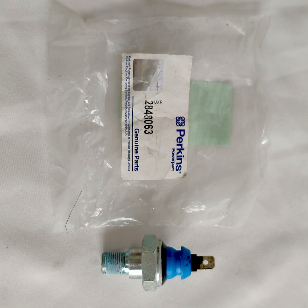
A sensor continuously outputs a signal that changes with the physical condition being measured. For example, an oil pressure sensor can provide a continuously changing pressure value for the ECM or instrument panel.
A switch does not provide a continuous measurement. It changes the electrical state of a circuit only when a defined condition is reached. A low oil pressure switch, for example, changes circuit state when pressure reaches its specified low-pressure threshold, allowing the system to activate a warning or engine shutdown.
Even when a sensor and a switch use the same or a similar threaded connection, they should not be considered interchangeable.
If a system requires a continuous pressure signal but a simple pressure switch is installed, the result may include:
- No valid pressure reading on the instrument panel;
- A warning signal that remains continuously active or never activates;
- An ECM input that does not match the expected signal type, preventing the protection or control logic from operating correctly.
Before ordering, determine whether the system requires a sensor that provides a continuous value or a switch that provides only an open-or-closed circuit signal. This distinction is more important than confirming the thread size alone.
2. The Same Measurement Can Use Different Signal Types
Components described as temperature sensors may measure different media, including coolant, lubricating oil, intake air, charge air, or fuel.
Even when two sensors measure coolant or oil temperature and have a similar housing and thread, they may use different output methods.
- Thermistor-type sensor: The resistance of the sensing element changes with temperature. The receiving system uses a reference voltage and measuring circuit to calculate the corresponding temperature.
- Active sensor with signal-conditioning electronics: The sensor is powered by the control system and produces an analog voltage corresponding to the measured temperature.
Although the two types may look mechanically similar, their power requirements, output characteristics, and receiving-system calibration can be different.
Installing the wrong type may cause the reading to remain fixed at an abnormal value or create a systematic error across the entire measurement range.
Pressure-measuring components can also use different output logic:
- Pressure switch: Changes circuit state when a specified pressure condition is reached;
- Resistance-type sender: Changes resistance as pressure changes and is commonly used with traditional gauges;
- Analog voltage sensor: Normally receives power from the control system and outputs a voltage that changes with pressure.
The correct type must be confirmed using the Perkins part number, current supersession information, wiring diagram, and documentation for the relevant control system.
Do not identify a pressure-measuring component solely by its appearance, and do not assume that all pressure sensors use the same output method.
3. Passive Inductive and Active Position Sensors Are Not Directly Interchangeable
Crankshaft and camshaft position sensors provide engine-speed and phase information to the ECM.
Two common operating principles are used. Their power requirements, output signals, and ECM input circuits are different, so they normally cannot be directly interchanged.
- Passive inductive sensor: Does not require an external power supply. As the teeth or slots of the target wheel pass the sensor tip, the sensor generates an alternating-current signal. Signal amplitude is affected by engine speed, sensor air gap, target-wheel design, and wiring condition. Correct air gap and complete wiring are especially important during low-speed cranking.
- Active position sensor: Requires an external power supply. Internal electronics convert changes in the magnetic field into a processed digital signal, allowing the sensor to provide clear position information at relatively low rotational speeds.
The connector shape may be similar, making the two sensors easy to confuse. However, one requires external power while the other does not, and their output waveforms are fundamentally different.
Installing the wrong type is not simply a matter of receiving a weaker signal. The ECM may be unable to detect engine speed or phase information at all, potentially causing a no-start condition or abnormal engine operation.
Magnetic Speed Pickups on Generator Sets
Where a magnetic speed pickup is installed near the generator-set flywheel ring gear, it is usually a passive inductive device.
Two separate mechanical parameters must be checked:
- Installation depth: How far the sensor enters the mounting hole;
- Air gap: The actual distance between the sensor tip and the flywheel teeth.
Installation depth affects the resulting air gap, but the two terms do not describe the same thing.
If the sensor is installed too deeply, the tip may contact the flywheel ring gear and suffer physical damage. If it is installed too shallowly, or if the air gap is excessive, the induced signal may be too weak, causing unstable speed readings or signal dropouts.
The required installation depth and air gap must be confirmed from the relevant equipment or control-system service information.
4. Identical Connectors Can Have Different Pinouts
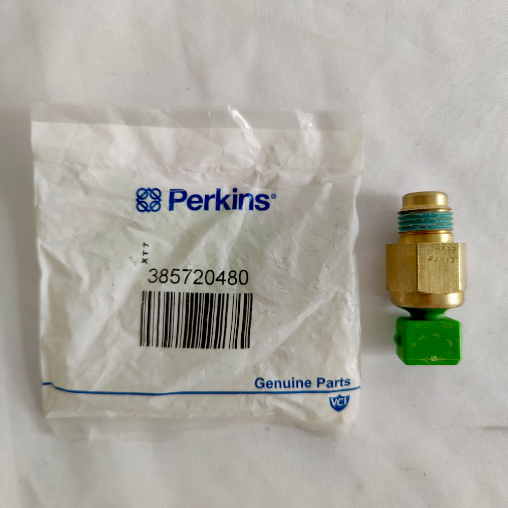
Two sensors may use connectors with the same housing design and the same number of pins, but the electrical function assigned to each pin can still be different.
For example, one three-pin sensor may use:
- Pin 1 for power;
- Pin 2 for signal;
- Pin 3 for ground.
Another sensor with an identical-looking connector may use a different arrangement.
If a replacement is selected only by connector appearance, it may plug into the harness without any physical resistance while the wiring functions are incorrectly aligned.
The consequences may include:
- Incorrect or unstable readings;
- No signal;
- Damage caused by connecting power to a signal terminal;
- Damage to the sensor or the related ECM input circuit.
During procurement, pinout compatibility should be confirmed using:
- The Perkins part number;
- The current valid superseding number;
- The engine Build List;
- The applicable wiring diagram.
Where onsite testing is required, a qualified technician should follow the wiring diagram to check the power supply, ground, circuit continuity, and output signal.
Pin functions should not be identified through connector appearance, guesswork, or trial connection.
5. Is Setup, Relearning, or Fault-Code Handling Required After Replacement?
Most common pressure, temperature, and speed sensors do not require an individual calibration code when the correct part number and engine configuration have been confirmed.
However, some electronically controlled systems may require additional work after installation:
- Read and record the existing diagnostic codes before clearing anything, then verify whether the fault remains after the repair;
- Check live data to confirm that the reading has returned to a reasonable range;
- Clear historical fault codes only when required by the relevant service procedure;
- Confirm ECM parameter or software compatibility only when specified by the service information;
- Perform a relearning or calibration procedure only for systems that specifically require one;
- Confirm the sensor air gap, installation direction, or mechanical reference position.
The required process depends on the engine model, Build List, control system, and sensor type.
It should not be assumed that every sensor requires individual calibration. It should also not be assumed that the job is complete as soon as the physical component has been installed, or that every replacement requires software-related work.
The correct procedure must be determined from the service information for the specific engine and control system.
6. A Sensor-Related Fault Code Does Not Prove the Sensor Has Failed
When a sensor-related diagnostic code appears, the first reaction is often to replace the sensor.
However, the code normally indicates that the ECM has received an abnormal signal. It does not automatically prove that the fault is located inside the sensor.
The same fault code may also be caused by:
- A damaged wiring harness;
- Poor or intermittent connector contact caused by moisture, corrosion, or vibration;
- A problem with the corresponding ECM input circuit.
If these areas are not checked, a replacement sensor may be installed and the same code may return because the actual fault has not been corrected.
The opposite situation is also possible. A sensor may have drifted out of specification or failed internally, while the fault description appears to indicate an open circuit, short circuit, or signal-out-of-range condition.
A diagnostic code should therefore not be treated as an automatic instruction to replace the sensor.
A more reliable diagnostic process is to:
- Review the exact definition and conditions of the fault code;
- Use the wiring diagram to check sensor power and ground;
- Check wiring continuity;
- Check for short circuits to power or ground;
- Measure the sensor output under the specified operating or reference conditions;
- Determine whether the problem is located in the sensor, harness, connector, or ECM input circuit.
Different sensor types require different testing methods.
A passive inductive sensor can be checked for coil resistance, but a normal resistance value does not prove that the dynamic signal is correct. Its AC output or waveform should also be checked while the engine is rotating.
An active sensor requires checks of its power supply, ground, and output signal.
For speed and position sensors, it may also be necessary to inspect:
- The dynamic signal waveform;
- The condition of the target wheel;
- The installation air gap.
These tests should be performed by technicians with the appropriate equipment and service information.
7. Installation Location Determines What the Sensor Measures
Pressure-measuring components installed upstream of the oil filter, in the filter housing, or in the engine main oil gallery do not necessarily measure the same pressure point.
Readings at different locations can be affected by:
- Filter restriction;
- Oil temperature and viscosity;
- Oil flow;
- Bypass-valve condition;
- The exact position of the measurement port.
Two pressure sensors should not be treated as having the same function simply because they use the same thread.
Temperature sensors installed at the cylinder-head coolant outlet, thermostat housing, or another part of the cooling circuit also measure temperatures at different points in the system. Their normal readings and control functions may therefore be different.
Installation location is part of the sensor specification, not merely a mechanical detail.
Engine-Mounted Sensors
These sensors are part of the original engine configuration and normally supply pressure, temperature, speed, or position information to the engine ECM.
They can generally be researched using:
- The engine serial number;
- The Build List;
- Perkins engine parts information.
Additional Generator-Set Control Sensors
Some generator sets use additional magnetic speed pickups, temperature switches, or pressure switches that supply information directly to the generator-set controller.
These components may not appear in the base-engine parts list. They may need to be confirmed using:
- The generator-set manufacturer;
- The controller model;
- The equipment wiring diagram;
- The actual onsite wiring configuration.
Before researching a replacement, determine whether the sensor is connected to:
- The engine ECM;
- The equipment controller;
- The instrument panel;
- The generator-set controller.
This determines whether the correct reference source is the engine parts documentation, equipment-manufacturer documentation, or generator-set control-system documentation.
8. What Should Be Confirmed When Comparing Quotations and Delivery Scope?
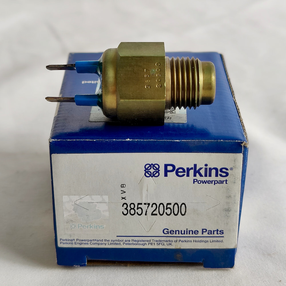
Different suppliers may use the general description “engine sensor” for quotations with different product and delivery scopes.
Before comparing prices, confirm:
- The quoted Perkins part number, historical part number, and current superseding number;
- Whether the product is a sensor, sender, or switch;
- The measurement location and signal type;
- Whether the connector pinout matches the existing harness;
- Whether O-rings, sealing washers, or installation accessories are included;
- Whether a connector repair kit or adapter harness is included;
- Whether the quotation covers a single sensor or a complete wiring-harness assembly;
- Whether fault-code handling, parameter checks, or installation adjustments may be required.
The lowest quoted price may not represent the same component or the same supply scope.
Information Required for Sensor Verification
To support an accurate parts review, provide:
- The complete engine model, engine serial number, and Build List;
- The required sensor type, such as speed, pressure, temperature, or position, together with its installation location;
- The Perkins part number, manufacturer number, or other identifiable markings on the removed component;
- Clear photographs of the sensor and its connector;
- The current diagnostic code or operating symptom;
- Confirmation of whether the harness and connector condition has already been checked;
- The engine application, such as construction equipment, a generator set, or another industrial system.
The application helps determine whether the sensor belongs to the engine ECM system or is an additional component used by the equipment or generator-set controller.
More complete measured data and fault information allow the correct configuration to be identified more efficiently.
Where complete information is not immediately available, a budgetary reference may be prepared from the engine model. Final confirmation, however, should be based on verified part information and the actual wiring configuration.
ZEB POWER can use the engine serial number, Build List, removed-component information, and available technical documentation to assist with confirming:
- The correct sensor version;
- The applicable engine configuration;
- The required signal type;
- The connector form;
- The quotation and delivery scope.
Pin assignments must be confirmed from the official wiring diagram for the relevant engine, equipment, or generator set.
Detailed fault-code diagnosis, harness and connector testing, and any specified setup or relearning procedure should be completed by technicians with the required diagnostic equipment and service information.
Frequently Asked Questions
If the Sensor Screws Into the Port and the Connector Plugs In, Does That Prove It Is Compatible?
No. Compatibility depends on whether the sensor output matches the input specification of the ECM, instrument panel, or controller. A component can fit physically while still producing an incompatible signal.
What Is the Difference Between an Oil Pressure Sensor and a Low Oil Pressure Switch? Can They Be Interchanged?
No. A pressure sensor provides a continuously changing pressure signal. A low oil pressure switch only changes circuit state when the specified pressure condition is reached. Installing the wrong type may result in no gauge reading or incorrect warning and shutdown operation.
Can Passive and Active Crankshaft Position Sensors Be Used Interchangeably?
No. They use different signal-generation principles. One normally operates without an external power supply, while the other requires power. The ECM input circuits are also different. Installing the wrong type may prevent the ECM from detecting engine speed or position.
Does a Sensor-Related Fault Code Mean the Sensor Should Be Replaced Immediately?
Not necessarily. A damaged harness, corroded connector, poor power or ground supply, or ECM input-circuit problem can produce the same code. These areas should be checked before the sensor is treated as the confirmed cause.
Is Any Additional Work Required After Installing a New Sensor?
It depends on the specific system. Most common sensors do not require an individual calibration code when the correct part number and engine configuration have been confirmed.
After the repair, however, the diagnostic information should first be read and recorded, and live data should be checked. Historical codes should then be cleared, or parameter checks and relearning procedures performed, only when required by the applicable service information.
It should not be assumed that every sensor replacement requires software-related work.
Are Magnetic Speed-Pickup Installation Depth and Air Gap the Same Thing?
No. Installation depth describes how far the sensor enters the mounting hole. Air gap is the actual distance between the sensor tip and the flywheel teeth. Installation depth affects the air gap, but the two parameters must be checked separately.
Is the Speed Sensor on a Generator Set Always Part of the Base Engine Configuration?
No. Some generator sets use an additional magnetic speed pickup dedicated to the generator-set controller. It may not appear in the base-engine parts list.
It is necessary to determine whether the required component supplies the engine ECM or was added as part of the generator-set control system.