

Cummins Engine Sensors: Which One Does Your Fault Code Point To?

7722
Table of Contents
Generating table of contents
When a warning light appears on the instrument panel or a diagnostic tool displays a fault code, the first question for many parts buyers is not, “How much does the sensor cost?”
It is:
Which sensor does this code actually refer to?
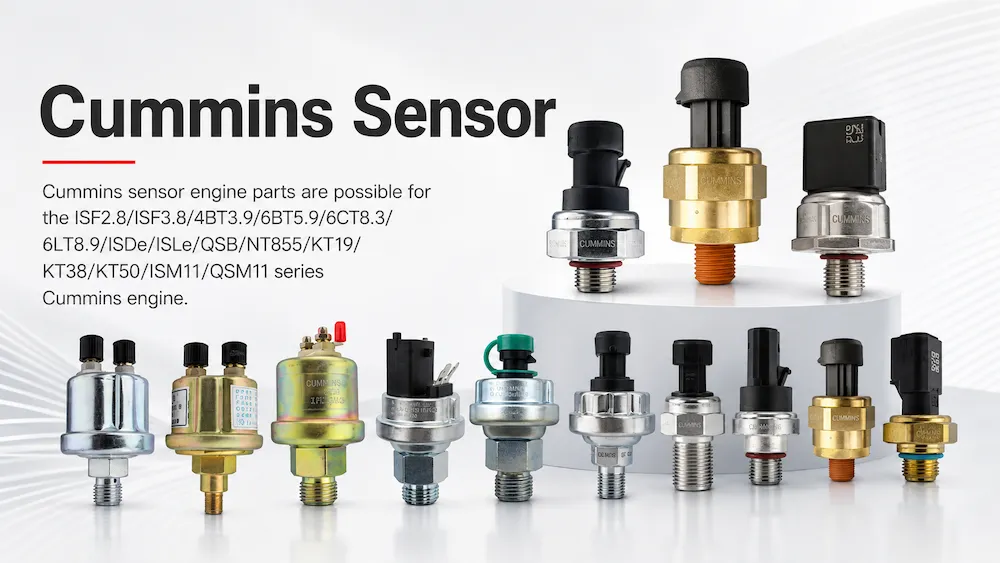
Oil pressure, coolant temperature, engine speed and exhaust pressure sensors are among the more commonly requested—and more frequently confused—sensor types used on Cummins engines. They are compact, many look similar, and some may even use connectors with a similar appearance.
Two sensors that look nearly identical may still differ in several important ways:
- The parameter being measured;
- Measurement range or operating range;
- Output signal type, such as voltage or resistance;
- Connector pin count or pin assignment;
- Probe length, even when the thread appears identical;
- Continuous-output sensor versus pressure or temperature switch;
- Original part number versus a superseding part number;
- Vehicle, construction equipment, generator set or other OEM configuration.
Ordering the wrong sensor may result in a part that cannot be installed. In more serious cases, it may lead the repair process in the wrong direction, leaving the original fault unresolved even after the part has been replaced.
This article does not explain how to test each sensor with a multimeter. Electrical testing and fault diagnosis should be carried out by technicians with the appropriate diagnostic equipment and service information.
Instead, this guide explains where these four sensor types are generally located, what they do, what symptoms may be associated with them and what information buyers should provide to avoid ordering the wrong part.
Quick Sensor Reference
| Sensor | Typical Location | Main Function | Commonly Confused With |
|---|---|---|---|
| Oil Pressure Sensor | Usually connected to a main oil gallery near the cylinder block, oil filter head or lubrication module | Monitors engine oil pressure and sends a signal to the ECM, electronic gauge or equipment controller | Oil Pressure Switch |
| Coolant Temperature Sensor | Usually installed in a coolant passage near the cylinder head or thermostat housing | Monitors coolant temperature and sends the signal to the ECM or instrument system | Coolant Level Sensor |
| Engine Speed / Position Sensor | Near the crankshaft, flywheel, camshaft or timing components, depending on the engine platform | Provides engine speed, crankshaft position, camshaft position or synchronization information to the ECM | Crankshaft and camshaft sensors being confused with each other |
| Exhaust Pressure Sensor | Connected to the exhaust manifold, an EGR-related passage or another exhaust pressure point, depending on the platform | Measures pressure at a specified exhaust location for air-management, EGR or emissions-control functions | DPF Differential Pressure Sensor or Boost Pressure Sensor |
Exact locations, connectors and sensor configurations vary by engine model, emissions level and CPL. This table is intended only as an initial reference.
Final part selection should be based on the engine serial number and the confirmed sensor part number.
Oil Pressure Sensor
The oil pressure sensor is connected to the engine lubrication system and monitors pressure in a main oil passage. It provides an oil-pressure signal to the ECM, electronic instrument panel or equipment controller.
When the signal is abnormal, the gauge may indicate excessively low pressure, excessively high pressure or no reading at all. The ECM may also record an oil-pressure-related fault code.
An oil-pressure warning should never be concealed by replacing the sensor without confirming the actual oil pressure.
Real oil-pressure problems may be related to:
- Incorrect engine oil level;
- Incorrect oil grade or viscosity;
- A restricted or unsuitable oil filter;
- Oil pump wear or damage;
- Pressure-regulating components;
- Internal oil-passage restrictions;
- Excessive bearing clearance;
- Other internal engine wear.
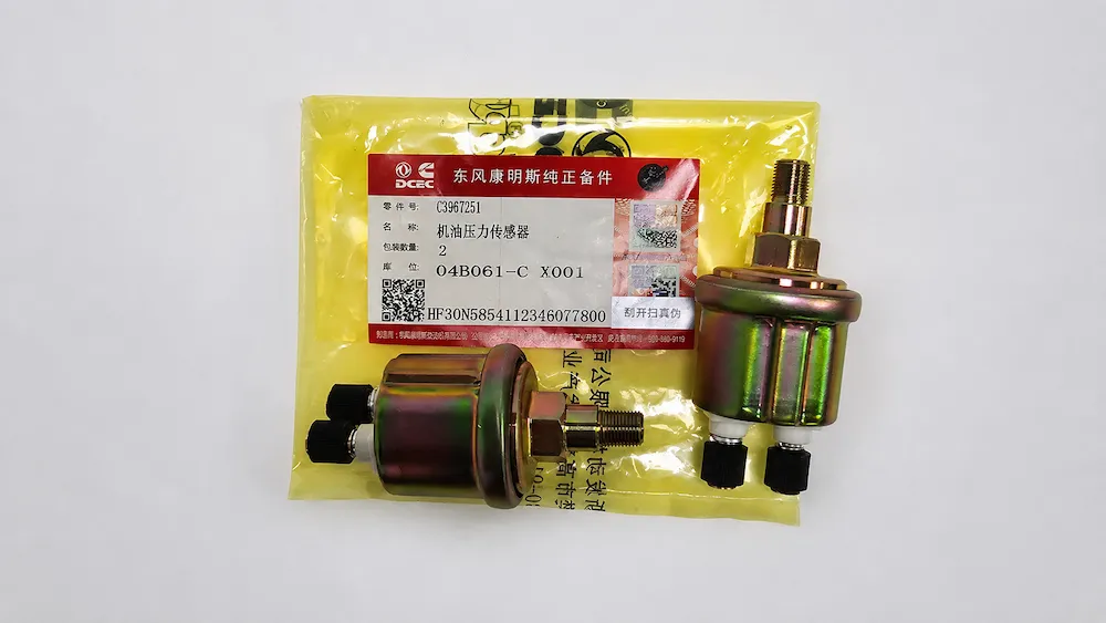
Another frequent source of confusion is the difference between an oil pressure sensor or sender and an oil pressure switch.
An oil pressure sensor or sender normally provides a changing signal that allows the ECM or gauge to monitor pressure continuously. An oil pressure switch usually changes state only when a specified pressure threshold is reached and is commonly used for warning or shutdown functions.
They are not automatically interchangeable, even when their installation positions and external appearance are similar.
When requesting a quotation, buyers should clarify whether the application requires a continuous pressure signal or a simple warning-switch function.
Coolant Temperature Sensor
The coolant temperature sensor is usually installed in a coolant passage near the cylinder head or thermostat housing. It measures coolant temperature and sends the information to the ECM, electronic instrument panel or another control module.
On many electronically controlled engine platforms, the ECM may use this signal for functions such as:
- Cold-engine operation;
- Fuel-control adjustments;
- Fan-control strategies;
- Engine protection;
- Derate or shutdown logic.
The exact functions vary by engine and control system.
A faulty or unreasonable signal may result in:
- Incorrect coolant-temperature readings;
- A gauge that remains too low, too high or does not move;
- Incorrect cold-engine or warm-engine recognition;
- Abnormal fan operation;
- Engine derate or protection events;
- Coolant-temperature-related fault codes.
However, an actual high-temperature condition may also result from:
- Thermostat problems;
- Water pump problems;
- Restricted radiator airflow;
- Fan or fan-clutch problems;
- Low coolant level;
- Poor coolant circulation;
- Excessive engine load;
- Other cooling-system faults.
A Coolant Temperature Sensor and a Coolant Level Sensor are also different parts.
The temperature sensor measures coolant temperature. The level sensor monitors the amount of coolant in an expansion tank, reservoir or another specified location.
Both may be described casually as a “coolant sensor,” but their functions are completely different.
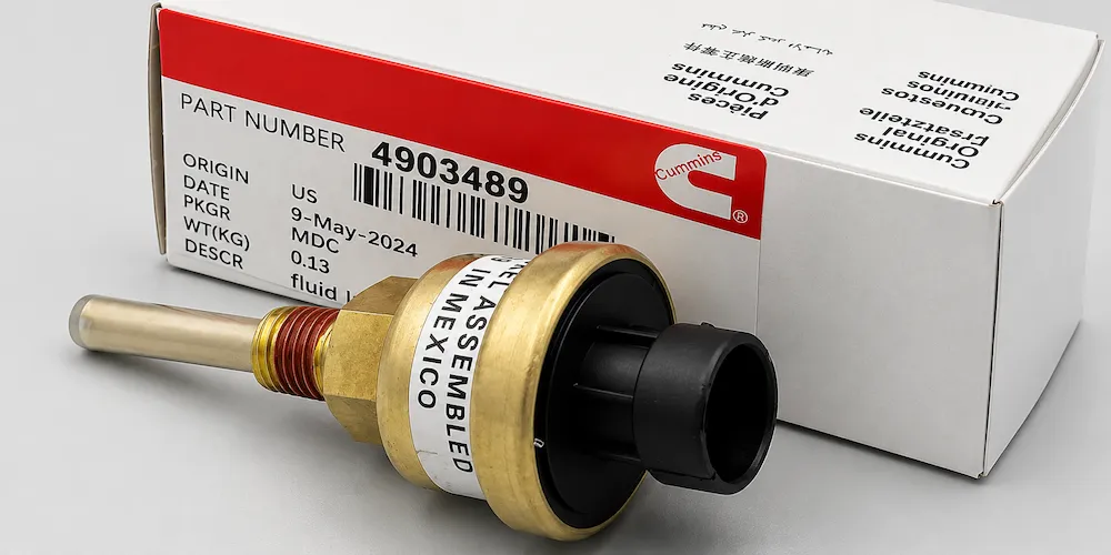
Some engines or equipment control systems may use more than one temperature-signal device. For example, the engine ECM and the equipment instrument panel may obtain temperature information from separate components.
A photo of the original installation position and connector is therefore more useful than a request that only says:
Cummins coolant temperature sensor.
Engine Speed and Position Sensors
Engine speed and position sensors provide information that allows the ECM to identify engine speed, crankshaft position, camshaft position and synchronization status.
These signals are essential for the starting and operation of many electronically controlled engines.
Many Cummins electronic engine platforms use a crankshaft speed or position sensor together with a camshaft position sensor. The ECM uses the signals to identify engine position and synchronize fuel injection.
The exact number, location and operating principle of these sensors vary by engine platform.
Possible symptoms associated with a lost or unreasonable speed or position signal may include:
- Engine cranks but does not start;
- Intermittent starting difficulty;
- Rough or unstable operation;
- Unexpected engine shutdown;
- Loss of engine-speed information;
- Speed- or synchronization-related fault codes.
A crankshaft speed or position sensor and a camshaft position sensor normally cannot be assumed to be interchangeable.
Even when they have similar housings or connectors, they may differ in:
- Part number;
- Probe length;
- Mounting arrangement;
- Signal function;
- Installation location;
- Sensor-to-target clearance;
- Applicable ECM configuration.
Selection should be confirmed using the engine serial number, installation position and formal part number.
On some platforms, the distance between the sensor and the flywheel, tone wheel or timing target is also controlled by a service specification. Installation procedures should be taken from the correct engine service documentation.
Exhaust Pressure Sensor
An exhaust pressure sensor may be used to measure pressure in the exhaust manifold, an EGR-related passage or another specified point in the exhaust system.
Engines equipped with emissions aftertreatment may also use a DPF Differential Pressure Sensor. This component measures the pressure difference between two points, normally upstream and downstream of the diesel particulate filter.
These are not the same type of sensor.
An Exhaust Pressure Sensor may monitor pressure at a single specified location. A DPF Differential Pressure Sensor compares pressure between two locations. A Boost Pressure Sensor measures pressure on the intake side of the engine.
They should not be ordered using the general description “pressure sensor.”
Possible symptoms associated with exhaust-pressure-signal problems may include:
- Exhaust- or EGR-related fault codes;
- Aftertreatment fault codes;
- Reduced engine power or derate;
- Abnormal DPF regeneration frequency;
- Incorrect exhaust-pressure readings;
- Engine-protection events.
Some exhaust pressure sensors are connected to the exhaust passage through a pressure tube, fitting or adapter.
In these applications, an abnormal signal may be caused by:
- Carbon buildup;
- A blocked exhaust pressure port;
- A restricted pressure tube;
- A leaking tube or fitting;
- A damaged connector;
- Wiring problems;
- Actual abnormal exhaust pressure;
- The sensor itself.
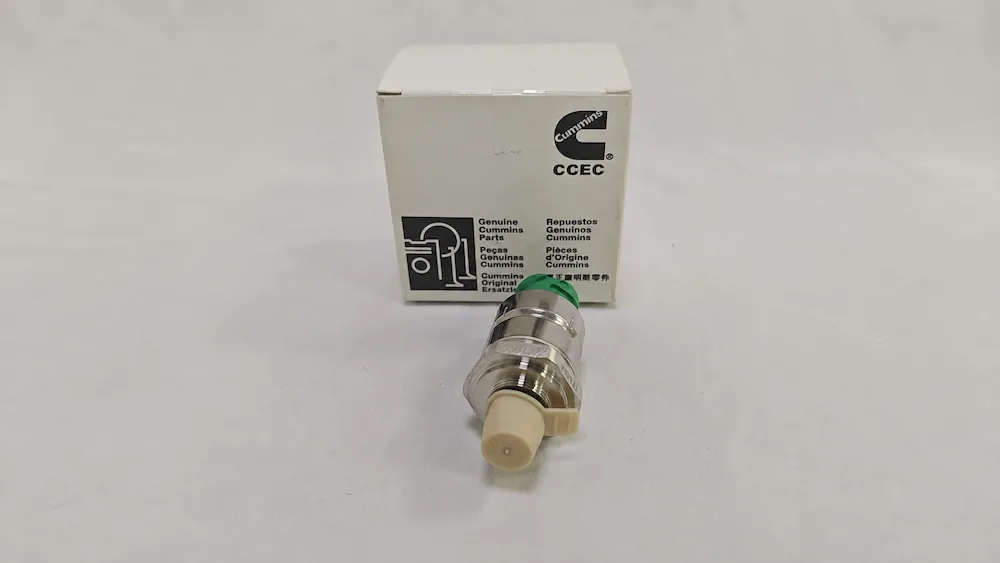
The sensor signal may be used by the ECM for EGR, aftertreatment, air-management or engine-protection logic. For this reason, the replacement part should be confirmed by formal part number, engine configuration and signal specification rather than by external appearance alone.
What a Fault Code Can—and Cannot—Tell You
A common purchasing mistake is to treat a fault code as proof that a sensor must be replaced.
A fault code may indicate:
- Which signal or monitored system is abnormal;
- Whether the signal is high, low, missing or unreasonable;
- The operating conditions under which the fault occurred;
- The general diagnostic direction.
However, a fault code usually cannot independently prove:
- That the sensor itself has failed;
- Which exact sensor part number should be ordered;
- Whether a superseding part number is directly compatible;
- Whether the wiring harness is damaged;
- Whether the connector has poor contact or corrosion;
- Whether the ECM reference voltage or ground is correct;
- Whether the engine has a real mechanical or system problem.
For example:
- An oil-pressure fault may reflect real low oil pressure;
- A coolant-temperature fault may occur during genuine overheating;
- An exhaust-pressure fault may be caused by a blocked pressure passage;
- A speed-signal fault may originate from wiring, installation clearance or another synchronization sensor.
The correct approach is to use the fault code as supporting information while also providing:
- Engine serial number;
- Original sensor part number;
- Installation position;
- Connector photos;
- Sensor photos;
- Equipment information.
The final diagnosis should be performed by technicians with appropriate service tools.
A fault code identifies the inspection direction. A part number identifies the purchasing item. They are not interchangeable.
How to Select a Non-Genuine Sensor
The market includes many products described as “universal” or “compatible” sensors.
For sensors connected directly to the ECM, a replacement should not be selected only because its housing, thread or connector looks similar to the original part.
A more practical distinction is:
- Genuine Cummins sensor;
- Qualified aftermarket sensor with a confirmed cross-reference and signal specification;
- Unverified product that only looks similar to the original component.
When selecting an aftermarket sensor, confirm that the supplier can provide:
- A clear cross-reference to the original part number;
- Measurement range;
- Output characteristics;
- Connector specification;
- Pin configuration;
- Thread and installation dimensions;
- Probe length where applicable;
- Applicable engine models or serial-number range;
- Warranty and traceability information.
A statement such as “fits Cummins engines” is not sufficient.
For equipment with high downtime costs, such as mining machinery or continuously operating generator sets, correct part-number matching is normally more important than the lowest unit price.
Extra care is required for exhaust-pressure and other emissions-related sensors. An incorrect signal may affect not only the displayed reading but also EGR, aftertreatment or engine-protection logic.
Information to Prepare Before Ordering
Sensors are small components, but their identification often requires more information than buyers expect.
To reduce the risk of ordering the wrong part, prepare the following details.
Engine Information
- Engine model;
- Engine Serial Number;
- CPL, when available;
- Engine nameplate photo.
Sensor Information
- Sensor type or monitored system, when known;
- Original part number;
- Superseding number, when already identified;
- Installation position;
- Whether the component is a sensor, sender or switch.
The customer’s description of the sensor type should be treated as a reference only. Final identification should still be based on the ESN, part number and installation position.
Required Photos
Provide clear photos of:
- Complete sensor;
- Part-number marking;
- Front of the connector;
- Connector pin count and arrangement;
- Side view of the connector;
- Thread and probe;
- Wiring-harness connector;
- Installation position before removal;
- Wider installation-area view;
- Engine nameplate.
Application Information
State whether the engine is used in:
- A truck or other vehicle;
- Construction machinery;
- Mining equipment;
- Agricultural equipment;
- Industrial machinery;
- A pump or compressor;
- A generator set;
- Another OEM application.
For generator sets, also clarify whether the sensor signal is connected to:
- The engine ECM;
- An independent generator controller;
- A shutdown panel;
- An equipment OEM monitoring system.
The same general sensor description may refer to different components depending on the control system.
Fault Background and Order Details
Also provide:
- Relevant fault codes;
- Warning or operating symptoms;
- Order quantity;
- Destination country;
- Genuine or qualified aftermarket preference.
Fault information helps explain the background of the request, but it does not replace formal part-number verification.
Frequently Asked Questions
A fault code points to a sensor. Should I replace the sensor immediately?
Not necessarily.
A fault code indicates an abnormal signal or monitored condition. The cause may be the sensor, wiring, connector, power supply, ground circuit or the system being monitored.
The fault should be checked by a qualified technician before a replacement part is ordered.
What is the difference between an oil pressure sensor and an oil pressure switch?
An oil pressure sensor provides a continuously changing signal that can be monitored by an ECM or electronic gauge.
An oil pressure switch changes state at a specified pressure threshold and is commonly used for warning or shutdown functions.
They should not be assumed to be interchangeable.
Is a coolant temperature sensor the same as a coolant level sensor?
No.
A coolant temperature sensor measures temperature. A coolant level sensor monitors the amount of coolant in a tank, reservoir or another specified location.
Both may be casually described as a “coolant sensor,” so the required function must be confirmed before ordering.
Can a crankshaft speed or position sensor be used in place of a camshaft position sensor?
Normally not.
The two sensors may have different installation positions, signal functions and part numbers. Selection should be confirmed by ESN, installation location and formal part number.
Can I use a non-genuine sensor?
A qualified aftermarket sensor may be considered when it has a confirmed original-part cross-reference and matching signal, connector and installation specifications.
Unknown “universal” sensors without clear cross-reference or technical data are not recommended.
Can I request a quotation without the old sensor part number?
Yes, an initial identification may still be possible.
Provide the engine serial number, approximate installation position, connector photos, complete sensor photos and equipment model. Final confirmation should still be completed before the order is released.
Need help identifying a Cummins Oil Pressure, Coolant Temperature, Engine Speed / Position or Exhaust Pressure Sensor?
Send the engine serial number, original part number when available, connector photos, probe and thread details, installation-position photos and related fault codes.
ZEB Power can assist with confirming the applicable part number and current supply options. Diagnosis of the sensor, wiring harness and the system being monitored should still be completed by qualified local technicians.